Now that is one fully loaded O2!  Looks great.
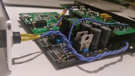
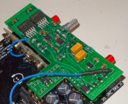
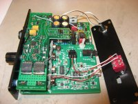
One suggestion - I would recommend twisting the black wires going to the AC plug to help keep any powerline hum out of the DC. Looks like it might be zip cable (the two wire bonded together). If so just unzip the full length of it then twist. You can probably twist it without un-mounting the jack by just rotating the rear panel a few times.
Looks great.One suggestion - I would recommend twisting the black wires going to the AC plug to help keep any powerline hum out of the DC. Looks like it might be zip cable (the two wire bonded together). If so just unzip the full length of it then twist. You can probably twist it without un-mounting the jack by just rotating the rear panel a few times.
Last edited:
Thanks agdr, that is a good suggestion. Although i don't get any audible hum.
Yeah, I was kind of lazy and used a piece of zip cable from an old acdc-adapter. It is pretty stiff, i should probably change it for something like the blue silicone wire you use. Where do you get that?
Actually, i am more concerned with the heat from the regulators, they hit about 60 degrees when i measured, so i guess it gets a bit toastier in the closed case. The cable runs between the case's side and the regulator at the edge of the board, probably making contact with it. Should i be concerned?
Skickat från min C6603 via Tapatalk
Changing the power wiring to something smaller and more flexible is a good idea. I'll drop some in the mail for you tomorrow, no charge. The blue stuff on the booster board is high strand count 24 AWG silicone insulated. I'm going to send you the same thing but slightly larger, the 22 AWG version, for the power wiring. The stuff is flexible as a wet noodle and the silicone insulation good for over 600 degrees F. Doesn't shrink back at all when soldered. You can run it right next to those voltage regulators with no problem.
You are OK on the regulator temperature. NwAvGuy and I went back and forth about that on PM here once back in the day. I was pointing out that I nearly burned my finger on one when running an O2 from 16Vac (more regulator voltage drop and hence power dissipation than the 12Vac transformer). He was quite adamant that the regulators are just fine at 200F (90C) based on the data sheet and since they are inside the case where they won't be touched it doesn't matter. My view was yeah, but if they are running that hot maybe that is nature's way of saying they should be heat sinked, for long term reliability's sake if nothing else. That whole thing is probably why I went a little nuts with heat sinking all the voltage regulators on my version of the ODA.
The blue stuff on the booster board is high strand count 24 AWG silicone insulated. I'm going to send you the same thing but slightly larger, the 22 AWG version, for the power wiring. The stuff is flexible as a wet noodle and the silicone insulation good for over 600 degrees F. Doesn't shrink back at all when soldered. You can run it right next to those voltage regulators with no problem.You are OK on the regulator temperature. NwAvGuy and I went back and forth about that on PM here once back in the day. I was pointing out that I nearly burned my finger on one when running an O2 from 16Vac (more regulator voltage drop and hence power dissipation than the 12Vac transformer). He was quite adamant that the regulators are just fine at 200F (90C) based on the data sheet and since they are inside the case where they won't be touched it doesn't matter. My view was yeah, but if they are running that hot maybe that is nature's way of saying they should be heat sinked, for long term reliability's sake if nothing else.
That whole thing is probably why I went a little nuts with heat sinking all the voltage regulators on my version of the ODA.
Last edited:
CHiroshi - I put the wire in the mail today. The post office here tells me it should be air mail all the way, so hopefully shouldn't take too long.
I was off by one notch on the wire gauges. The blue stuff on the Booster Board is actually 26 AWG while what I'm sending is the 24 AWG. Both are the high strand count blue silicone insulated stuff.
Congratulations on your build!
The post office here tells me it should be air mail all the way, so hopefully shouldn't take too long. I was off by one notch on the wire gauges. The blue stuff on the Booster Board is actually 26 AWG while what I'm sending is the 24 AWG. Both are the high strand count blue silicone insulated stuff.
Congratulations on your build!
Thanks agdr, that's really very kind! Paypal-invoice me if you want me to buy you a beer!
But where do you get this wet noodle stuff anyways?
The wire is on me, but I'll have a beer regardless to celebrate your build!

I bought the 26 gauge wire from flaminpyro over on Laser Point Forums here (scroll down one page). He has it in all sorts of colors. Even though the wire is just 26 gauge it has 64 strands of 44 gauge inside, making it super flexible and high ampacity for the size.
The 24 gauge I bought from an eBay vendor here. If that link goes away the eBay heading is "Super Flexible 24AWG Blue High Temp Silicone Wire RC Plane FPV Quadcopter 3' 6'"
Looks like I wasn't remembering correctly about the temperature rating. Both are rated for 200C, which is around 392F rather than 600F. Still way more than is needed for running next to the O2 regulator heat sinks though.
The temperature rating is one thing to be careful about with silicone wire. Some of it doesn't have a high temperature rating like these do. A soldering iron will shrink it back, similar to PVC. I've bought some of the low temp stuff before by mistake and wound up tossing it in the trash. Radio control model places sell the 24 AWG but the 26 AWG is really hard to find.
Last edited:
...but I'll have a beer regardless to celebrate your build!
Cheers! Don't forget, you are the one who actually did the hard work soldering the surface mount stuff!..
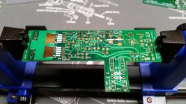
Agdr, thanks for the wire! I also bought a few different colors 26awg from the laser pointer forum. Might come in handy for new projects. I am thinking of tidying up my odac wiring by removing three of the battery terminals and rerouting the wires through the empty holes. It is getting crowded in there with the booster!
Forgot to mention I shorted across the 1R resistors at the outputs. I will post more pictures next time I open the case!
Forgot to mention I shorted across the 1R resistors at the outputs. I will post more pictures next time I open the case!
CHiroshi - I'm glad the package made it through the mails! I did the same thing with the 26 AWG, I bought several different colors from him a while ago to have on hand. The 26 AWG is great stuff.
Yeah those O2 battery terminals are not needed for anything anymore. The O2 booster has a wire that solders onto one of the middle two battery terminals. If you remove them just solder the wire in the hole where one of the terminals was.
Hey good for you on shorting the 1R's! I'll bet many folks with booster boards haven't noticed that in the build instructions and/or implemented it. Those 1R output resistors on the O2 board are not needed anymore since there is just one big current buffer chip on each channel now, rather than two small ones in parallel. Might was well have nearly 0R out vs. 0.5R.
CHiroshi - I'm glad the package made it through the mails! I did the same thing with the 26 AWG, I bought several different colors from him a while ago to have on hand. The 26 AWG is great stuff.
Yeah those O2 battery terminals are not needed for anything anymore. The O2 booster has a wire that solders onto one of the middle two battery terminals. If you remove them just solder the wire in the hole where one of the terminals was.
Hey good for you on shorting the 1R's! I'll bet many folks with booster boards haven't noticed that in the build instructions and/or implemented it. Those 1R output resistors on the O2 board are not needed anymore since there is just one big current buffer chip on each channel now, rather than two small ones in parallel. Might was well have nearly 0R out vs. 0.5R.
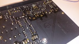
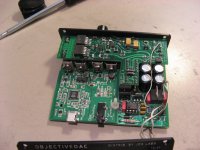
Tidying things up!
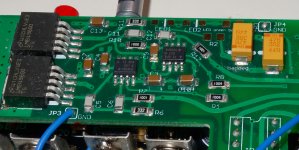
1. Unsoldering the battery terminals. Note the shorts to the output resistors
2. At first I was thinking of leaving one terminal for stability. It looked kind of funny and I decided against my own advice to remove it too!
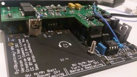
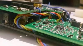
3. Nice 26 awg wet silicon noodle cable!
4. More silicon goodness! 24 awg provided by agdr for the AC power!
Attachments
Solder paste...
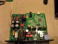
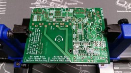
Just completed my Booster and agdr thought I should post photos of my build. The reason - instead of wire solder, I was using solder paste.
Solder paste is easy to use. You spread a bit on the PCB solder pad, a bit to the pin, position the part on the board, apply heat with solder iron for 3 seconds then you are done.
I was doing it in a rush. Did the whole thing in less than a hour. I am sure you can do a much better job if you do it in a slower pace.
Benefits of using solder paste:
* Easy to work with SMD parts, especially with ICs, almost fool proof.
* Perfect joins, no overflow, no spill.
* Efficient. You can solder a lot of SMD parts in a few minutes.
Attached are photos of my Booster.
Attachments
I am impressed with the way finneybear's soldering paste job turned out! I've avoided paste because I've thought a toaster oven was the only way to make it work, but he did it with an iron. I'm definitely going to have to give that a try.
finneybear says that the paste drys out fairly fast, so buying small quantities is the best way to go.
finneybear says that the paste drys out fairly fast, so buying small quantities is the best way to go.
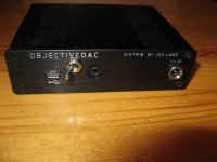
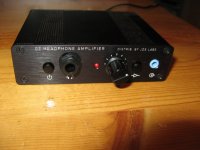
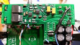
Completed my O2 with AGDR Booster and ODAC. A very compact full feature Desktop DAC and headphone Amp
I'm using custom Front and Back panels from JDS Labs. The front has the option full size jack and no power input jack that is now on the back. The full size headphone jack was particularly a challenge to fit with the booster. But it fits.
The back has the AC power input and the internal ODAC usb and audio output jacks. I added a small switch that allows me to send the ODAC audio directly inside to the O2 input or not, freeing the O2 front input if I choose so.
Attachments
Last edited:
Completed my O2 with AGDR Booster and ODAC. A very compact full feature Desktop DAC and headphone Amp
WOW - you managed to get a full size headphone jack in there! I am just amazed at all the creative ways folks find to customize the O2 and booster board. Even a switch in back for the ODAC! My very first version of the booster board had a full size 1/4" headphone jack mounted upside down above the O2's power jack, but I had to remove it when I added the relay circuitry. But you found a way to get one in anyway.
I like those custom panels!
I had sent you a PM before seeing your post here about running that JP4 wire up from the bottom of the booster board. Never mind - I see why you didn't now. That is right where the 1/4" jack is at. Another way to do it (to avoid having to run that wire around the front of the booster board) may be to run the wire on the top of the booster board to that corner by the battery terminal, then run it back under the board there along side that 1/4" jack to the front of the O2 board where it solders.
I would also make the same suggestion as above in post #301 to twist the wires going to the rear power jack. That will help make sure no AC hum radiates into anything.
You have a very nice looking unit there, inside and out.
Last edited:
Good tip - skip the text fill to save some money on panels!
A big thanks goes out to Algar_emi for making me a aware of an interesting pricing thing with Front Panel Express. Turns out their color fill for the text engraving is pretty pricey. Setting that parameter to "no fill", so that just the aluminum shows through the engraving, lops off several dollars!
A big thanks goes out to Algar_emi for making me a aware of an interesting pricing thing with Front Panel Express. Turns out their color fill for the text engraving is pretty pricey. Setting that parameter to "no fill", so that just the aluminum shows through the engraving, lops off several dollars!
Last edited:
Just finished my O2 and booster build and wanted to share some pics and build tips for others out there. I'm going to break this up into 2 posts, first the O2 board build. (I'm sure some of this has been posted before)
1) Defiantly go to agdr's website and read the pages on "modern parts upgrade for O2" and "simple and easy modifications for O2". You will see a few things different from my O2 and the standard build based on those pages.
2) Buy the stupid DIP IC sockets. NwAvGuys lists them as optional for the O2 build but they are required for the connection between the booster board and the O2. (this delayed by build by a week)
3) If you're like me and getting the front and back panels from JDS Labs with power and RCA on back, make sure you buy their isolated power jack and rca jacks. They cost a little more than comparable at mouser, but they fit the holes. I tried NwAvGuys jacks from the BOM but they were too big for the JDS holes.
4) If going with the 5k pot option by agdr, the O2 BOM volume knob will be the wrong shape and will not fit. (I'll have to order a knob on my next mouser purchase)
5) Use milk of magnesia (MoM) as anti-seize for the case screws. When I built another amp, the screws broke on me leaving the shaft suck in the enclosure and I had to get another enclosure. MoM dries out and even acts as an aluminum anti-corrosion too.
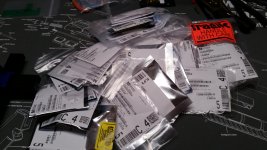
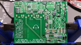
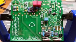
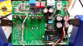
The pics below are all the parts dumped from the mouser box and blank board from agdr, then with small resistor and diodes, then with small caps, then finished. I tested very briefly with the standard NJM4556AD op amps before using the booster board so I can't say much about the O2 sound other than it works.
1) Defiantly go to agdr's website and read the pages on "modern parts upgrade for O2" and "simple and easy modifications for O2". You will see a few things different from my O2 and the standard build based on those pages.
2) Buy the stupid DIP IC sockets. NwAvGuys lists them as optional for the O2 build but they are required for the connection between the booster board and the O2. (this delayed by build by a week)
3) If you're like me and getting the front and back panels from JDS Labs with power and RCA on back, make sure you buy their isolated power jack and rca jacks. They cost a little more than comparable at mouser, but they fit the holes. I tried NwAvGuys jacks from the BOM but they were too big for the JDS holes.
4) If going with the 5k pot option by agdr, the O2 BOM volume knob will be the wrong shape and will not fit. (I'll have to order a knob on my next mouser purchase)
5) Use milk of magnesia (MoM) as anti-seize for the case screws. When I built another amp, the screws broke on me leaving the shaft suck in the enclosure and I had to get another enclosure. MoM dries out and even acts as an aluminum anti-corrosion too.
The pics below are all the parts dumped from the mouser box
and blank board from agdr, then with small resistor and diodes, then with small caps, then finished. I tested very briefly with the standard NJM4556AD op amps before using the booster board so I can't say much about the O2 sound other than it works.Attachments

Now some tips for the booster board.
1) Get a wide chisel tip for your soldering iron. While it is possible to do with a normal tip, it's much harder. (I know the directions point this out, but I just wanted to emphasize)
2) Crank up that heat for the 2 LME49600 chips!!! Really easier to more heat less time for these 2 than less heat more time. The copper pads underneath the chips will suck all the heat from the soldering iron.
3) Don't cut the cord agdr sends you with the 1M resistor in it I had to do a repair on my cord cause I cut it by accident (which is why you see the electrical tape on the cord running across the top)
4) If you use the 827 op amps like i did, the tiny little circle on the chip really is marking pin 1. Normally the dot is solid white and more in the corner, but on these chips, its a circle with another circle inside it and more towards the center. Just looking at it without magnification, it looks like a really small copyright symbol. I had to get out a 10x to make sure that was the dot that marks pin 1.
5) Solder all the jumper wires without the boards "sandwiched" together. Pretty sure the instructions had the other way and I just found this to be easier.
If you've never done any diy before.... TRY THESE. Both builds are not that difficult and really fun, plus a good learning experience.
I will be comparing my O2 + booster to my ODA to see if I can hear any differences. Will post later on that subject, till then, cheers!
1) Get a wide chisel tip for your soldering iron. While it is possible to do with a normal tip, it's much harder. (I know the directions point this out, but I just wanted to emphasize)
2) Crank up that heat for the 2 LME49600 chips!!! Really easier to more heat less time for these 2 than less heat more time. The copper pads underneath the chips will suck all the heat from the soldering iron.
3) Don't cut the cord agdr sends you with the 1M resistor in it
I had to do a repair on my cord cause I cut it by accident (which is why you see the electrical tape on the cord running across the top)4) If you use the 827 op amps like i did, the tiny little circle on the chip really is marking pin 1. Normally the dot is solid white and more in the corner, but on these chips, its a circle with another circle inside it and more towards the center. Just looking at it without magnification, it looks like a really small copyright symbol. I had to get out a 10x to make sure that was the dot that marks pin 1.
5) Solder all the jumper wires without the boards "sandwiched" together. Pretty sure the instructions had the other way and I just found this to be easier.
If you've never done any diy before.... TRY THESE. Both builds are not that difficult and really fun, plus a good learning experience.
I will be comparing my O2 + booster to my ODA to see if I can hear any differences. Will post later on that subject, till then, cheers!
Attachments
- Home
- Amplifiers
- Headphone Systems
- O2 headamp output booster PCB