V3.1 schematic, build instructions, and BOM pricing updates. Post #1 update.
Thanks go out to ukhopeful for bringing some updates needed to the most current V3.1 O2 booster board project materials to my attention. These are changes that had been discussed in the posts above and made on the BOM, but I hadn't gone back to the schematic and build instructions since May to update them.
Specifically:
* The 1 meg series resistor that goes from the JP6 hole on the O2 booster board to the R8 resistor on the O2 PC board is now properly shown on the schematic and discussed in the build instructions. I had O2 PCB "R25" on there instead of "R8" for connecting the wire, which has now been corrected. From the discussion in the posts above remember that you can use either the end of R8 that is closest to the O2 voltage regulators for attaching the booster sense wire, or the end of R25 closest to the edge of the O2 PC board. Both are the same circuit point on the O2. R8 is the preferred attach point though just because the distance is shorter.
* The build instructions still talked about C17, which was the pad for a much larger (47uF) timing capacitor to be placed across the C16 2.2uF timing cap. C17 was eliminated in V3.1 so that writeup has now been corrected. C16 is currently 2.2uF, which gives about 3 seconds of O2 turn-on delay to get rid of the O2's turn on thump. The schematic and build instructions still had mention of some previous timing cap values that gave longer delays (that I since found were not needed) of 4.7uF and 10uF. Everything now references just 2.2uF.
* The timing resistor R13 also had the old R12 label in the build instructions, before a board re-number was done, which has now been corrected.
* Several small text reformats and moves on the schematic to make things clearer and easier to read.
I've also gone through the entire BOM again vs. Mouser's current stock to update the prices and check on stock availability. The good news is that prices have changed very little, just 3 parts or so had changes. A few of the alternate op-amps listed at the bottom of the BOM had price changes. Everything on the O2 booster board is in stock at Mouser but the relay - still - they still show availability in September. Digikey has them and I have a bunch here.
I've also updated the first post in this thread to bring it current. The current booster board is V3.1. A link to the project's Google Drive folder with sub-folders for all the project materials is given in that first thread post. I've moved the project files for the older versions into an "archived older versions" folder to make it clearer which folder has the current stuff vs. the older stuff. I had pulled the folders for those older versions off a month or so ago when I received some email from folks who were getting confused and using the wrong project version files for their V3.1 build.
Last edited:
Just an update, my booster board has been working perfectly since the repairs I did a few months back. Thanks again AGDR🙂
Just an update, my booster board has been working perfectly since the repairs I did a few months back. Thanks again AGDR🙂
Good to hear! Thanks for the feedback. 🙂
I've come up with a couple of theories on why the booster seems to subjectively sound better (in my completely biased opinion, lol).
First off is that reduction in bass on the O2 with the AC cord pulled out. I've built up a couple more O2's recently and I'll just swear I can hear a drop in bass while running on batteries vs. AC. It isn't subtle either. Yet I've made some fairly precise amplitude measurements of low frequencies sinusoids on the O2 on AC vs. batteries and they are just exactly the same output levels.
So whatever is going on seems to happen with real music but not single tone sinusoids, which just breaks by brain right there. Strange stuff. One thing I realized is that voltage drop between AC and batteries may be affecting something, +/-12Vdc vs. the +/-9Vdc or so with the batteries. I can't see that having an effect on any passive part in the O2 schematic, which leaves one or more of the op-amps possibly not behaving well at the lower voltage.
I don't hear that bass drop off with the AC plug pulled out using the booster board. That makes me think the NJM4556A output chips could be the culprit. I even went as far as to swap the gain chip back and forth with a LME49990 on an adaptor board a few times and don't hear the bass drop off with that swap. So it looks like the booster board may not have that (purely subjective, my ears) assumed problem with the voltage change between AC and batteries that the NJM4556A may be having, even though it is datasheet-rated for even lower voltages.
As for what, electrically, that problem with the NJM4556A chip at lower supply voltage might be, I have no clue. Slew rate comes to mind since it is only 3V/uS, maybe that is dropping with lower applied rail voltage, but I can't think of a IC-internals way to even make that happen. Plus slew should only really alter high frequencies and not low. The output transistors in the NJM4556A are going to have a harder time at a lower voltage for a given output load, making the feedback more important. Maybe something is going on there.
Then the other interesting thing is potentially a op-amp source resistance induced THD problem with the O2 volume control at mid-volume. This tech problem here:
http://cds.linear.com/docs/en/design-note/dn84f.pdf
The first round of ODA dScope testing showed a slightly elevated THD level at mid volume control. Tracking that one down my best guess at the moment is this issue. If I'm right, then the O2 may have 10x the problem since its volume control is 10K vs. the 1K in the ODA. Mid volume control in the O2 would then put the two 5K control halves in parallel in the AC model (one half returns to the gain stage output of 0V and the other to ground of 0V, both considered AC shorts), or 2.5K directly in series with the NJM4556A output chip inputs vs just 250 ohms for the ODA. From the Linear Tech paper in that link 2.5K is more than enough to cause the problem in some op amps.
The booster board uses the FET input op amp - OPA140 and OPA827 - which may be more immune to the problem. Interestingly enough it appears that NwAvGuy never did a dScope THD+N test at half volume control in his plots here:
NwAvGuy: O2 Headphone Amp
They are all done at full volume control, which would put the input to the output NJM4556A chips directly connected to the gain stage output. 0 ohms in series and the problem wouldn't show up. His only half volume control plot was just for noise floor. He may have just missed this one. I would have too if not for a post here on the forum a month or two ago about the issue. I've sent an O2 to Mike at Audio Circle for half volume control dScope testing as his time permits. We'll see! This will be interesting.
should i get a booster board
I'm considering the booster for my o2 for running it with a par of he-560 headphones. (50 ohms @ 90 db/mW
)
currently it dosn't go quite lout enough at the 2.5x gain setting and the 6x setting clips.
though it is fine with my other headphones, - 600 ohm seinnhisser and a pair of 32 ohm grado's
I bought the amp pre built (should have just built it myself) o2 / odac and it came with a triad mau-12-200 12v 200ma power supply (13.3v measured unloaded), I noticed clipping on the 2.5x gain setting when using the odac, and figured out that was caused by an under spec'd power supply. so that was an easy fix now using a supply with a 15.5v no load voltage rated at 1000ma.
does it sound like the booster would be appropriate?
should any consideration be given to the power section of the o2 - in example, should the voltage regulators be heat slinked if using the booster? (as I saw a comment some limits to the o2's power section)
also this o2 has a 6.3mm headphone jack in a standard case, will there be clearance problems with the booster board.
thanks
Last edited:
I'm considering the booster for my o2 for running it with a par of he-560 headphones. (50 ohms @ 90 db/mW
)
currently it dosn't go quite lout enough at the 2.5x gain setting and the 6x setting clips.
Good questions! It sounds like your primary problem is that you just need a little more gain (than 2.5x) in the high gain position, not all the way up to 6.5x. To do that just replace R19 and R21 on your O2 with 620 ohm resistors. i've attached a picture below. Those resistors are Mouser part #270-620-RC. They should also be avalable at most local electronics supply outfits, although please try to get "metal film" if possible rather than "carbon" or "metal oxide" resistors - there is a noise difference. They would give you a gain of (1 + 1500R/620R) = 3.4 in what was the 6.5x gain position.
With your HE560 headphones the booster board would be helpful for musical peaks. To hit 120dB sound pressure level (SPL) the HE-560s would need a voltage swing of 7.1Vrms and 141mA(rms) of current per channel. The O2 can swing up to 7Vrms while running on AC, so no real problem there. While on batteries the O2 can only swing a maximum of 4.5Vrms, which with your headphones would "only" take it to 116dB SPL, but that is still extremely loud and should only be listened to for very short musical peaks anyway. So in summary no voltage output swing problem really with the O2 and your HE560s.
BUT the 141mA current requirement is a problem. 140mA is the near the absolute maximum current each of the O2's NJM4556A chips can supply (around 70mA for each of the dual amps in the chip, then in parallel). An even bigger problem is power dissipation. Each chip can dissipate around 700mW. About 300mW of that is taken up by idle current while on AC, in other words the chip just sitting there doing nothing. That leaves 400mW total for the music. Well at 7V swing you would have (12 - 7) / 70mA = 350mW, but then times two for both sections. That give 700mW, more than the 400mW, leaving your output chips about 50% over their maximum power dissipation.
Luckily that is just for musical peaks, but if you have sustained peaks your output chips can wind up like this fellow's:
JDS O2 blew an op-amp (pic inside). Question regarding replacement.
Nothing at all wrong with the O2 build there, it is a design issue. NwAvGuy didn't really make clear in this blog that some low-impedance low-sensitivity headphones (like your HE560's) + higher volume levels + sustained and high musical peaks can, in fact, overheat the output chips. The closest he comes to saying it is in his blog noting that "While I’ve abused the O2 in a variety of ways playing real music into assorted worst case loads, and it has survived nicely, it will eventually overheat the output op amps with sustained high power sine wave (or square wave) testing into low impedance loads". Higher volume levels and sustained musical peaks approach sine-wave amounts of power dissipation.
So...to summarize.. a booster board would definitely help in your case. The output chips can burst up to 250mA on musical peaks, not just 140mA, and you can see from the math above that for your particular headphones that matters. The output chips in the booster board can also dissipate a bit more heat, although just like NwAvGuy says in the quote above sustained sine wave testing would overheat them too, just as with the O2 chips, but they do have more power dissipation available for peaks in normal music listening (not sine waves). I think there has been a bit of confusion out there on this point, of what the booster board was designed to do. It gives you a lot more current output range for peaks in music, but is definitely not intended to sit there and be happy with sine wave testing. 🙂 If someone wants that build an ODA - or AMB b22 - or anything else with large heat sinks, lol. 🙂
The booster board gives you other useful stuff like the headphone relay which eliminates any remaining O2 turn-on or turn-of thumps. It adds two green LEDs that are after the O2 mosfets which show you immediately if your mosfets have turned on, and that both power rails are OK. And with the DC precision FET input chips (OPA140 or OPA827) you get a DC output on your headphone outs of around 100 microvolts, vs. around 3700 microvolts typical in the O2. So low that DMMs that only measure down to 1 millivolt will probably show zero volts DC on the output. That feature keeps your headphone drivers right at their natural "idle" resting position, rather than 3.7mV to one side or the other.
As for the power transformer, you still probably don't have the right one. Get a WAU12-1000 (or WAU12-1500, I see Mouser has those priced a little lower for some odd reason). The problem there is exactly what you say, the O2's voltage regulators are not heat sinked and there is no easy way to get a heatsink on them (I do have a mod for that in my O2 mod thread here, heatsinking them to the back panel, but it is involved). So it is best to stay at 12Vac input even if that means the voltage regulators may go into dropout on some musical peaks. NwAvGuy and I exchanged some PMs about that once and he was adamant that the PSRR (power supply rejection ratio) of the chips are high enough that the vregs going into dropout makes no difference on his dScope testing. He is the man with the dScope so I'll have to take his word on that. 🙂
Going to 15.5Vac probably will overheat the voltage regulators in your case since that puts 3 move volts across each. People with headphones pulling much less current than your HE560s can get away with higher voltage transformers to keep their vregs out of dropout at all times, like 16Vac or 20Vac, since the current through the vregs is smaller even if the voltage drop across them is larger (vreg power = voltage drop * current through them). But in your case the currents are much larger and the vregs would get unacceptably toasty. That original WAU12-200 just isn't enough current for your phones, given the 2.5x de-rating factor for the transformer secondary given the half wave rectifier current spikes.
As for your 6.3mm jack, if it is in the back no problems with the booster board. If it is in the front it would likely interfere. However I keep forgetting to post that I did get some longer connection pins that would allow the booster board to be used in the taller B3-080 case, which may solve that problem, if the jack would wind up between the booster board in the top B3-080 slot and the O2 board on the bottom.
Attachments
Last edited:
Thanks, that was a great explanation. I'll give the resistor change a try before opting for the booster. see how that goes.
I did have some thoughts as you were explain the issues and resolutions.
Relocating the regulators to the case wouldn't be a big deal id think but I had an idea of using copper straps as a poor mans heat pipe to the case ... no wires running around to pick up noise. But It seems like it makes sense to get the heatsinked somehow if under extra load like in my case.
I did get a peak inside the amp today. I'm highly disappointed with who built it. I have to re wire there "modifications" so might as well just relocate the regulators while I am at it. I'll check out your mod as reference thanks.
similarly, has anyone put heatsinks on the opamps or even thermally connecting the opamp to the case using a copper strip to increase dissipation? would seem like a relatively easy way to get some extra dissipation.
the higher current lower voltage power supply makes sense considering the current requirements peak, and trying to keep the dissipation down on the regulators i'll do that.
Thanks, that was a great explanation. I'll give the resistor change a try before opting for the booster. see how that goes.
Sounds good, that may very well solve your problem. The 140mA is for very loud 120dB musical peaks. Average/normal listening levels would be far below that, well within the NJM4556A chip's capabilities.
Copper straps/bars on the vregs are a good idea! Just remember to include an insulating washer at some point to keep the tabs from making electrical contact with the case.
The vreg mod I did is here . The last two photos in the post show the results.
I did do a mod that heatsinked the two output chips, the third item on the list here . The last photo shows them, although kind of hard to see. The heatsinks are Avvid 580100B00000G which have a thin bar that slides under the chip while the rest of the heatsink contacts the top. Mouser and Digikey don't stock them, but Future electronics and Jameco do: 580100B00000G: 8 Pin DIP Slide on Heat Sink: AAvid Thermalloy
The heatsinks fit in there rather amazingly, although I had to slightly bend a fin on one to clear the filter caps. I would probably recommend hot-gluing one fin on each to the filter caps for added stability. The heatsinks get warm so heat is being transferred.
Last edited:
I love the booster board even though my Sennheiser HD580s don't need the extra peak current. The zero turn on/off noise and reduced dc offset was well worth the extra money and I think it sounds better then a stock O2 even though the measurements are very similar. If you can get some lme49600 and opa827 samples from TI you can build the booster board for under $50. That being said I think with power hungry headphones like the Hifimans the O2(with or w/o booster) is going to be pushed pretty close to its limits so maybe its a better choice to put the money into building a more powerful amp like ODA. That's just two cents😀
Then the other interesting thing is potentially a op-amp source resistance induced THD problem with the O2 volume control at mid-volume. This tech problem here:
http://cds.linear.com/docs/en/design-note/dn84f.pdf
The booster board uses the FET input op amp - OPA140 and OPA827 - which may be more immune to the problem. Interestingly enough it appears that NwAvGuy never did a dScope THD+N test at half volume control in his plots here:
NwAvGuy: O2 Headphone Amp
They are all done at full volume control, which would put the input to the output NJM4556A chips directly connected to the gain stage output. 0 ohms in series and the problem wouldn't show up. His only half volume control plot was just for noise floor. He may have just missed this one. I would have too if not for a post here on the forum a month or two ago about the issue. I've sent an O2 to Mike at Audio Circle for half volume control dScope testing as his time permits. We'll see! This will be interesting.
Systems ought to always be tested as a 'system' and not only as individual pieces connected to a test generator. Then, many things, such as, the Zo of your system will shows its contribution/affects.
THx-RNMarsh
Systems ought to always be tested as a 'system' and not only as individual pieces connected to a test generator. Then, many things, such as, the Zo of your system will shows its contribution/affects.
THx-RNMarsh
Very true! With the O2 headamp though the volume control is in the middle, between the gain stage and a parallel op-amp output current buffer stage. Here is the schematic:
https://docs.google.com/viewer?a=v&...NGJlNC00ODlmLWIwM2MtNDI4ZWU4YWRjY2Y4&hl=en_US
Hey if any of you guys with an AP would be willing to test the NJM4556A chip for input impedance distortion in a non-inverting config w/ 1x and 2.5x gain - 2.5K in series with the input vs. 0R - just let me know and I'll send you some chips. 🙂
Last edited:
Very true! With the O2 headamp though the volume control is in the middle, between the gain stage and a parallel op-amp output current buffer stage. Here is the schematic:
https://docs.google.com/viewer?a=v&...NGJlNC00ODlmLWIwM2MtNDI4ZWU4YWRjY2Y4&hl=en_US
Hey if any of you guys with an AP would be willing to test the NJM4556A chip for input impedance distortion in a non-inverting config w/ 1x and 2.5x gain - 2.5K in series with the input vs. 0R - just let me know and I'll send you some chips. 🙂
I am away from my lab/test equipment. I am hanging out in my condo in Bangkok at this time or would try some measurements for you. However, as many output Z rise in Z with freq - so still would be best to measure with your own specific source's Zo characteristics. But, generally, keep your Zo as low as possible.
THx-RNMarsh
Last edited:
I am away from my lab/test equipment. I am hanging out in my condo in Bangkok at this time or would try some measurements for you. However, as many output Z rise in Z with freq - so still would be best to measure with your own specific source's Zo characteristics. But, generally, keep your Zo as low as possible.
THx-RNMarsh
Good advice! I see that NwAvGuy did most of his dScope measurements with a fairly low source Z of 25 ohms.
New FPE CAD O2 Headamp front panel for the O2 Booster Board w/ green LEDs
I just remembered that I never did post these Front Panel Express CAD files for an O2 Headphone Amplifier front panel which includes the 2 holes for the O2 Booster Board green LEDs. The Booster Board LEDs sit above the O2's one red LED. I've posted the CAD files below in a zip file, along with the instructions in the README in that zip and some JPEG images of the result. I've also posted the same out at the project's Google Drive link in the first post in this thread.
There are two choices here. You can either have Front Panel Express use their own anodized aluminum or you can send in one of the blank panels that come with the case. I highly recommend the latter, even though it takes more time to ship a blank panel to FPE in Seattle. The blank panels the come with the case have the edges color-anodized to match the case and are rounded. Looks great. If FPE uses their own material the edge wind up square and bare aluminum. FPE only knocks a couple of dollars off the price if you send in your blank panel, plus you now have the cost of mailing the blanks to them, so it winds up being a couple of dollars more in total but worth it.
The blank panels that come with the B2-080 case already have the mounting holes already drilled in the corners, so that is why two different CAD files for their Front Panel Designer program in the zip. The send_blank file has the corner holes removed for use with sending the blank case panel to FPE. The other CAD files does specify drilling corner holes for use with FPE's own material.
The FPE's Front Panel Designer CAD program is a free download here. Once installed you just open up either of those .fpd CAD files in the zip, then go to the "order" tab -> "order current front panel" and place your order.
If you are sending in the blank panel just write down the order number it emails to you and put that on the outside and inside of the box. You also need to include in a note inside that the origin is the intersection of the left edge and bottom of the panel, with the bottom being the long edge where the corner mounting holes are farthest away from the long edge. The holes are asymmetric on the Box Enclosures panels, with the "top" having the mounting holes closer to the long edge.
FPD ignores the color setting on file-> "front panel properties" if you use the send_blank CAD file for sending in blank panels. If you are using the other CAD file and FPE's own material you set your panel color there. Their blue is a great match to the Box Enclosure blue, and of course black is black. I haven't had opportunity to test the color match on any other colors though. Again that is a big plus of sending in the blank panel from the case - the color match will be exact! Using FPD you can edit any of the text on these panels before submitting the order, of course. Delete text, add text, change font or font size, bold, italic, etc. 🙂
Attachments
-
O2 panel with booster board LEDs.zip180.9 KB · Views: 87
-
 O2 Booster panel FPD CAD using FPE material.JPG271 KB · Views: 335
 -
 O2 Booster panel FPD CAD mailing blank panel to FPE.JPG258.2 KB · Views: 332
 -
 IMG_3189.JPG152.3 KB · Views: 305
 -
 IMG_3190.JPG136.4 KB · Views: 298
 -
 IMG_3191.JPG162.9 KB · Views: 295
 -
 IMG_3192.JPG130.9 KB · Views: 126
Last edited:
A possible commercial model or kit...
I was browsing through Reddit today where I was excited to read that it is now legally acceptable for derivations of the Objective 2 amplifier design. ( http://www.reddit.com/r/headphones/comments/27amp9/john_from_jds_labs_says_any_customized_o2_or/ ) I am now looking for people to openly join together to express interest and pledge to buy this booster board accessory from commercial Objective 2 manufacturers.
I'm quite excited for this to get off the ground. As a first step, I have emailed John at JDS Labs to begin talks with him to see how much customer support he would need for this to be cost effective so he could begin setup and production. In the meantime, I am asking for each of you to start spreading the word among friends on- and off-line.
A few quick ground rules so this doesn't turn people off. Please be mindful of rules about advertising and spam on each site. For example, once someone has already posted about this on Head-Fi, please try to keep your comments expressing support to that thread alone. Safer, more effective options include PM'ing friends and sharing this via social media, such as Facebook and Twitter.
Here's something you could say: "The historic Objective 2 amplifier is almost ready to reach a new level of performance with the revolutionary Booster Board accessory, but I need you help to make this happen. If enough users pledge to buy this accessory, manufacturers may be willing to begin production. Please help by up-voting and sharing this. For more information on the Objective 2 Booster Board, see here: John from JDS Labs says "any customized O2 or O2+ODAC is possible now"...at last, the desktop O2 is reality? : headphones "
Thank you everyone for your enthusiasm and support! I'll keep you posted on all updates as they roll in.
Last edited:
I was browsing through Reddit today where I was excited to read that it is now legally acceptable for derivations of the Objective 2 amplifier design. ( John from JDS Labs says "any customized O2 or O2+ODAC is possible now"...at last, the desktop O2 is reality? : headphones ) I am now looking for people to openly join together to express interest and pledge to buy this booster board accessory from commercial Objective 2 manufacturers.
I'm quite excited for this to get off the ground. As a first step, I have emailed John at JDS Labs to begin talks with him to see how much customer support he would need for this to be cost effective so he could begin setup and production. In the meantime, I am asking for each of you to start spreading the word among friends on- and off-line.
A few quick ground rules so this doesn't turn people off. Please be mindful of rules about advertising and spam on each site. For example, once someone has already posted about this on Head-Fi, please try to keep your comments expressing support to that thread alone. Safer, more effective options include PM'ing friends and sharing this via social media, such as Facebook and Twitter.
Here's something you could say: "The historic Objective 2 amplifier is almost ready to reach a new level of performance with the revolutionary Booster Board accessory, but I need you help to make this happen. If enough users pledge to buy this accessory, manufacturers may be willing to begin production. Please help by up-voting and sharing this. For more information on the Objective 2 Booster Board, see here: John from JDS Labs says "any customized O2 or O2+ODAC is possible now"...at last, the desktop O2 is reality? : headphones "
Thank you everyone for your enthusiasm and support! I'll keep you posted on all updates as they roll in.
EDIT: The link in the message is incorrect. Please use this one instead. Thank you.
http://www.diyaudio.com/forums/headphone-systems/244473-o2-headamp-output-booster-pcb.html
I was browsing through Reddit today where I was excited to read that it is now legally acceptable for derivations of the Objective 2 amplifier design.
Thanks for posting the link! Interesting. I'm not on Reddit and hand't seen that.
My read though is that he is referring to just moving external panel-mounted jacks around the case, not any changes to the O2 PC board. I hadn't seen reference to the blog post from Head N' HiFi before, but it sounds like he has just remounted existing components on the existing O2 PC board to clear space for that panel mounted 1/4" jack.
The O2 Booster Board here is an attempt to get around any concerns about the O2's license by just plugging an accessory board into the existing O2 PC board. You can just take any existing O2 PC board, unplug the 2 NJM4556A chips, plug in the O2 booster board, solder 3 wires, and away you go. 🙂 Undoing it and reverting back to the original O2 is just the reverse of those simple steps.
You probably won't get a positive response from JDS, or any response at all. A few posts back in this thread, earlier in the year, he and I wound up with a bit of a disagreement on testing methods after he volunteered to dScope test the board. He did full power sine wave testing on a board I sent and apparently posted over on Head-Fi that it got hot. My response was well, yes, that is exactly what happens if you run full power sine waves for an extended period. The board is not designed with withstand full power since wave testing for extended periods. Same with the O2. NwAvGuy noted in his blog that full power sine wave testing of the O2 should be limited to 10 minutes, then the chips allowed to cool. With actual music, not continuous sine waves, the average levels are 2x - 3x below peak levels. In other words, with real music and real headphone loads the O2 booster board works just great.
A fellow had volunteered to dScope test the ODA a few months ago. I've recently had to give up on that one too. 🙁 From my experiences so far I've concluded that I really need to do any testing directly, myself, and have started acquiring some more equipment. I not going get involved with any 3rd parties for tests going forward.
Your best bet is to just DIY an O2 Booster Board yourself. 🙂 All the files are here in the first post in this thread. I still have some of the most recent V3.1 boards and will still sell them at cost plus actual postage if anyone is interested. Mouser is out of stock on the relays but Digi-Key has them and I have a bunch I will sell at-cost.
The Gerber files I've released for the O2 Booster Board are done with a version of a layout editor that is licensed just for DIY usage and they are watermarked that way. I also have a separate commercial license that I use for assembled boards. See my thread in the vendor bazaar forum here if anyone is interested in those.
Last edited:
Thanks for posting the link! Interesting. I'm not on Reddit and hand't seen that.
My read though is that he is referring to just moving external panel-mounted jacks around the case, not any changes to the O2 PC board. I hadn't seen reference to the blog post from Head N' HiFi before, but it sounds like he has just remounted existing components on the existing O2 PC board to clear space for that panel mounted 1/4" jack.
The O2 Booster Board here is an attempt to get around any concerns about the O2's license by just plugging an accessory board into the existing O2 PC board. You can just take any existing O2 PC board, unplug the 2 NJM4556A chips, plug in the O2 booster board, solder 3 wires, and away you go. 🙂 Undoing it and reverting back to the original O2 is just the reverse of those simple steps.
You probably won't get a positive response from JDS, or any response at all. A few posts back in this thread, earlier in the year, he and I wound up with a bit of a disagreement on testing methods after he volunteered to dScope test the board. He did full power sine wave testing on a board I sent and apparently posted over on Head-Fi that it got hot. My response was well, yes, that is exactly what happens if you run full power sine waves for an extended period. The board is not designed with withstand full power since wave testing for extended periods. Same with the O2. NwAvGuy noted in his blog that full power sine wave testing of the O2 should be limited to 10 minutes, then the chips allowed to cool. With actual music, not continuous sine waves, the average levels are 2x - 3x below peak levels. In other words, with real music and real headphone loads the O2 booster board works just great.
A fellow had volunteered to dScope test the ODA a few months ago. I've recently had to give up on that one too. 🙁 From my experiences so far I've concluded that I really need to do any testing directly, myself, and have started acquiring some more equipment. I not going get involved with any 3rd parties for tests going forward.
Your best bet is to just DIY an O2 Booster Board yourself. 🙂 All the files are here in the first post in this thread. I still have some of the most recent V3.1 boards and will still sell them at cost plus actual postage if anyone is interested. Mouser is out of stock on the relays but Digi-Key has them and I have a bunch I will sell at-cost.
The Gerber files I've released for the O2 Booster Board are done with a version of a layout editor that is licensed just for DIY usage and they are watermarked that way. I also have a separate commercial license that I use for assembled boards. See my thread in the vendor bazaar forum here if anyone is interested in those.
I came across that Head n' HiFi post on Reddit and it managed to perk my interest considerably in the possibility of a commercial board and it does not matter to me if it is preassembled or unpopulated, so long as it is made more accessible to people like myself. It is such a pity, however, that my short moment of excitement and enthusiasm over this has gotten an earlier curtain call, because, as you suggested would happen, I was told by JDS Labs that this board is problematic for the reasons you outlined. It is very sad for me that this dream has to be put to rest, but I am happy to see there is an eBay seller offering the booster board for a reasonable price that I may take him up on. I have one question, however. Are there any other perhaps "more" transparent or honest test calculations available of the booster board that I could look at? I am especially interested to see how this fares in the real world when it is properly tested.
That would be me listing that board. I looked up the cost of the main components on Mouser and that's what i listed it for so the PCB and assembly is free 🙂 Its a once off listing though as i built a v3 board which i am currently using, the v2 board just needs a good home..
I was told by JDS Labs that this board is problematic for the reasons you outlined.
For some more proof that opinion is wrong, take a look at opc's Wire headphone amp board here . Scroll down to the second picture labelled "SE-SE". Those are the same two LME49600 chips with about the same spacing between them and the same or less copper foil heatsink area. A boatload of people have built the Wire, including me, and it works great. Again with real world music as opposed to continuous full power sinewave testing.
I am happy to see there is an eBay seller offering the booster board for a reasonable price that I may take him up on.
Hey there you go, mcandmar's V2.0 board would be a good deal! The V2.0 board doesn't have the relay to eliminate the turn-on/turn off thumps, but then again a lot of O2s are better about that than others. The 4th part change down for C16 and C21 on this list I made of O2 part updates often helps reduce on/off thumps, going to higher precision 0.022uF caps.
. Are there any other perhaps "more" transparent or honest test calculations available of the booster board that I could look at? I am especially interested to see how this fares in the real world when it is properly tested.
Not yet, at least on a dScope of Audio Precision THD+N analyzer.
Last edited:
Hi folks!
This my first post ever here at diyaudio, and it is a success story!
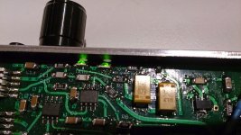
Last year I stumbled upon NwAvGuy's blog and decided to build his HPA. I bought two kits from Stefan at Head'n'hifi. One of them I built with the low power options, for commuting and music listening at work. The other one started as a standard version, to which i later added an ODAC. I have now agdrized it 😉, first with some of his suggested component upgrades (mostly caps), and now with a booster board! It sounds terrific, both objectively and subjectively speaking! 😀
Since I have little soldering experience (the O2s were my first serious projects) I decided to purchase a pre-assembled board. Many thanks go to agdr for his great work and generosity when sharing information, that's really much appreciated!
For starters, I swapped the (great) NJM2068 for a MUSES8820. It is an interesting chip with very similar specs to the 2068, but it is supposed to be JRC's audio nirvana... No surprises there, to my ears, It sounds every bit as great and transparent as the 2068! Subjectively, it sounds better, of course... 😛
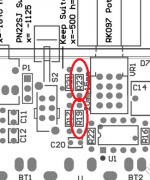
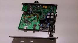
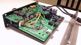
The booster board's installation went smoothly. I just had to reflow the solder joints for C13 and C14, as they were not properly seated on the O2's PCB, and the booster board wouldn't fit correctly as a result. Still, even after that, it is a tight fit. the LME49600 make contact with the case (which I guess helps dissipating heat! ), so do the big tantalum caps as well. The pre-assembled board I bought from agdr comes with all the options, such as the relay and the leds, and it has the OPA827.
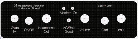
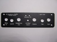
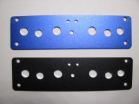
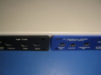
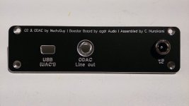
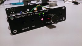
Finally, I decided my pimped O2 deserved some custom made plates! I hade these made by Schaeffer AG in Germany. I let the pictures speak for themselves, I am pretty happy with the results!
This my first post ever here at diyaudio, and it is a success story!
Last year I stumbled upon NwAvGuy's blog and decided to build his HPA. I bought two kits from Stefan at Head'n'hifi. One of them I built with the low power options, for commuting and music listening at work. The other one started as a standard version, to which i later added an ODAC. I have now agdrized it 😉, first with some of his suggested component upgrades (mostly caps), and now with a booster board! It sounds terrific, both objectively and subjectively speaking! 😀
Since I have little soldering experience (the O2s were my first serious projects) I decided to purchase a pre-assembled board. Many thanks go to agdr for his great work and generosity when sharing information, that's really much appreciated!
For starters, I swapped the (great) NJM2068 for a MUSES8820. It is an interesting chip with very similar specs to the 2068, but it is supposed to be JRC's audio nirvana... No surprises there, to my ears, It sounds every bit as great and transparent as the 2068! Subjectively, it sounds better, of course... 😛
The booster board's installation went smoothly. I just had to reflow the solder joints for C13 and C14, as they were not properly seated on the O2's PCB, and the booster board wouldn't fit correctly as a result. Still, even after that, it is a tight fit. the LME49600 make contact with the case (which I guess helps dissipating heat!
), so do the big tantalum caps as well. The pre-assembled board I bought from agdr comes with all the options, such as the relay and the leds, and it has the OPA827.Finally, I decided my pimped O2 deserved some custom made plates! I hade these made by Schaeffer AG in Germany. I let the pictures speak for themselves, I am pretty happy with the results!
Attachments

- Home
- Amplifiers
- Headphone Systems
- O2 headamp output booster PCB