4x4F150 - hey thanks for the build photos and notes! Your soldering really looks good. You have those two green LEDs lined up well. It always takes me a half dozen re-heats on each one to get it lined up in all three axes (the Z axis being flat on the board, they always seem to land at some angle on the first pass).
Yeah it is just amazing the difference the chisel tip makes. Same soldering iron with the same heating element (80W soldering station), but with the fine(r) tip I usually use it will only melt a small spot of solder around the tip contact point on the LME49600 tab. Swap over to a wide chisel tip and in 2-3 seconds the solder under the entire tab is melted.
Please do post your listening impressions! 🙂
Last edited:
ODA vs O2 + booster board listening comparison (non-scientific):
My DAC, the Fiio D03K, has 2 outputs: RCA and 3.5mm. I used that 1 device to feed the sound to both the ODA and O2. So in this comparison the only equipment difference was the cord and amp. Everything else was the same. I simply stacked the amps and pulled the 3.5mm headphone jack from one amp to the other many... many times.
So there's the connections for each:
Computer -> Optical Cable -> Fiio D03K -> 3.5mm -> ODA -> Hifiman HE400
Computer -> Optical Cable -> Fiio D03K -> RCA -> O2 + booster -> Hifiman HE400
Short version: They sound great and the same. OK... that was a really boring review. If you care any more about my opinion see long version below.
Long version: I tried to remain as objective as possible and I volume matched both amps as best as I could. Since I built both amps within the last 4 months, I really don't have any bias for one or another. It's not like I built the ODA and bought the O2 or other way around and would naturally think the one I built was better. Nothing like that going on here.
If one sound difference did exist, I can kind of say is that the sound stage seems deeper on the ODA than the O2. And what I mean by that is the "speaker" sounds slightly farther away on the ODA which then seems like you get a little more detail. But every time I said to myself, "hey there is something I didn't hear on the other amp", I would switch back and then notice the exact same sound. It was only the immediate switch where I would notice the difference, and then they would seem to sound the same. And I think much of the sound difference on the changeover is the "thump" you get from pulling the phones from one jack and plugging into another.
I tried every genre of music imaginable, everything from the Beatles, Green Day, Muse, Aretha Franklin, Lady Gaga, Mumford and Sons, Disturbed, Mozart, Eminem, Fall Out Boy, Korn, The Doors, ACDC, MGMT, CCR, STP, MSMR, REM and every other all caps band you can think of. (Sorry just can't listen to country tho) Everything I played sounded identical, other than that initial switch. And I have to stop comparing before I wear out the headphone jacks on my brand new amps 🙂
Some physical differences: one thing I noticed immediately is that the 3.5mm jack on the ODA is SOOOOO much better than the 3.5mm jack on the O2. The O2 cost less to build (~$100 less) so that's a definite advantage to the O2 with sounding so similar. The O2 could be used as a portable amp where the ODA can't, but the ODA has more I/O connections, so that's a push. I wouldn't say the ODA was harder to build, but it took more time than the O2 + booster board...just more parts to solder on the ODA.
I might buy a switching I/O device like this one on amazon and get a helper for a blind test in the future. Amazon.com: Sescom SES-IPOD-AB iPod Stereo Audio MP3 FLAC WMA Player A/B Switch 3.5mm (1/8): Electronics. Since this is a passive switch I can use it for both input switching (DAC comparison with same amp) and output switching (amp comparison with same DAC)
In summary, both devices are great and can recommend either to anyone.
Thanx for the test and review, great info!
Another interesting test IMHO would be the original O2 vs the ODA, since both use the same good old 4556!
The reasoning behind that is the unmodded O2 should be the benchmark.
Would be really great if somebody organised a real blind test comparing the whole family, O2, O2 low power, O2 + booster and ODA!
4x4F150 - A big thanks for the review! 🙂
One thing to listen for is lack of background noise/hiss on the ODA vs. the O2 when the volume is all the way up with the highest gain switch setting, sensitive headphones, and the input grounded (nothing plugged into the 3.5mm jack and the input selector switch set for the 3.5mm). With the stock O2 I can hear faint, but still there, hiss with the volume and gain all the way up and sensitive phones. I don't hear any with the ODA, not even on the highest gain settings.
Same goes for the booster board *if* the 5K pot modification has been made to the O2 and the NJM2068 swapped out for the dual LME49990 (same gain chips as the ODA). Which reminds me - I know in your case those mods have been made, so your basic O2 now should already be less noisy than a stock O2. So... what you really need is a 3-way listening test one of these days that also includes the ODA vs. stock (unmodified) O2 and the modified O2 + booster board vs. the stock O2. 🙂
Last edited:
One thing to listen for is lack of background noise/hiss on the ODA vs. the O2 when the volume is all the way up with the highest gain switch setting, sensitive headphones, and the input grounded (nothing plugged into the 3.5mm jack and the input selector switch set for the 3.5mm). With the stock O2 I can hear faint, but still there, hiss with the volume and gain all the way up and sensitive phones. I don't hear any with the ODA, not even on the highest gain settings.
Just tried this out with some very sensitive IEM. Definitely hiss with the O2 + booster board on highest gain with no input plugged in. And absolutely nothing on the ODA on even a higher gain (8x ODA vs 6.5x O2) with no input plugged in (the ODA switched to the 3.5 input).
I can even hear some very tiny, tiny hiss on the O2 + booster on the lower gain, max volume (2.5x). I wouldn't even dream of playing music at either of those levels with the IEM though. They would probably blow both the IEMs and my eardrums 😱
There is no doubt that I would be able to tell 100% of the time in a double blind between the amps with no source and max volume, max gain.
What's up?
Did you ever get the dscope measurements from JDS?
Oh, just realized nobody has posted in months. Oh well, lol.
Did you ever get the dscope measurements from JDS?
Oh, just realized nobody has posted in months. Oh well, lol.
There have been some measurements I will defer to AGDR, but the ODA is my first choice over the O2.
Then there is the new inverting O2 version which is very good as well!
Alex
Then there is the new inverting O2 version which is very good as well!
Alex
No valid dScope or AP measurements with proper test conditions have been made by anyone on an "O2 + booster board" combo, at least that I've seen published.
I'm not interested in trying to go through any 3rd parties for measurements. I'm getting a Q401 analyzer when they are out and I'll post those results.
I think everyone who had interest in a booster board has built them by now. 🙂 A lot of folks got boards last year here and some I had posted on a website. But I don't think anyone has asked about a booster board in a couple of months. I should remind anyone out there who may be interested that the Gerber files are posted along with all the DIY project materials (schematic, layout, part ID diagram, BOM, build instructions). You can have PC board(s) made yourself.
Last edited:
Oh wow, I thought I posted in the ODA thread. I'm dumb. XD
Lol! 🙂 Too many threads with variations on the "O2" now. 🙂 mgalusha over on audio circle did do an initial set of dScope measurements on the ODA. It slightly beat the O2 in THD, but the main thing is that level contiunued out to nearly 3x the output current capability of the O2, as I recall.
I certainly appreciated Mike's efforts there. He has a very busy schedule and wasn't able to perform any follow-up tests, but just that initial set was extremely helpful.
I'ved learned the importance of being hands-on with the THD+N test gear. I may eventually just rent and AP for a couple of months and do some tests, after I've had a chance to do a round with the QA401.
Its been nearly two years since I built the booster board and it's still working perfectly, just wanted to give you guys and update and thank AGDR once more for a great design🙂
Since RocketScientist disappeared AGDR has taken up the mantle and provided us all with some really neat updates, upgrades and totally new design ideas!
I have built the ODA and the Inverting type of O2 and they work wonderfully!
Thanks AGDR!
Alex
I have built the ODA and the Inverting type of O2 and they work wonderfully!
Thanks AGDR!
Alex
Wow - has it been 2 years already? 😱 How time flies!
Hey thanks for the interest you guys have had in the project. I think it turned out really well. Nothing I would change, even to this day. I'm still amazed that the spacing between the top of the top-slot board and the top of the case just happened to be enough for LME49600's.
Big thanks on the project to Mr X for recommending those connection pins, Sergey888 for the 2nd order feedback network and the suggestion of the power line filters on the op-amp, and of course NwAvGuy for his O2 to plug the board into! 😀
Adgr, the Booster board was such a nice addition to the 02! Do you still have any boards left, populated or unpopulated?
CHiroshi - I just took a look. I have 2 bare PC boards left and 4 boards with all the parts soldered on except the two op-amps, so that either OPA827 or OPA140's could be soldered on (I would suggest using the OPA827). If anyone should be interested in a board just send me a PM. 🙂 The at-cost price of the bare board plus the connection pins that go between the booster board and the O2 is $14 plus actual postage and paypal's fee.
For the bare boards I also have the LME49600's here at-cost, TI has discontinued all those National parts now. I just did a BOM scan at Mouser and they appear to have all the other parts in stock at the moment.
For the boards with all the parts soldered on send me a PM. 🙂
For the bare boards I also have the LME49600's here at-cost, TI has discontinued all those National parts now. I just did a BOM scan at Mouser and they appear to have all the other parts in stock at the moment.
For the boards with all the parts soldered on send me a PM. 🙂
Last edited:
Texas Instruments is dropping chips
The Texas Instruments LME49990 and LME49610 chips are at End-Of-Life.
It's difficult to obtain these chips at a reasonable DIY price. Is there a
substitute chips for each? Will they work with the present set of PCB's?
Can you substitute another chip for these End-Of-Life chips? Will they work
in your present PCB design?😕
I always hate when a company stops making a set of great chips.

Does Texas Instruments have drop in replacements for these two chips?

What we need is information. The work of a DIY designer is never done.🙁
The Texas Instruments LME49990 and LME49610 chips are at End-Of-Life.
It's difficult to obtain these chips at a reasonable DIY price. Is there a
substitute chips for each? Will they work with the present set of PCB's?
Can you substitute another chip for these End-Of-Life chips? Will they work
in your present PCB design?😕
I always hate when a company stops making a set of great chips.
Does Texas Instruments have drop in replacements for these two chips?
What we need is information. The work of a DIY designer is never done.🙁
Good question! 🙂 For the O2 booster board here, which uses a OPA827 (or OPA140) looped with an LME49600 current buffer on each channel, the DPAK (TO-263) version of the BUF634 should work in place of the LME49600. Although I haven't tried it yet to be sure. 🙂 I also have a bunch of the LME49600s here I'll sell at-cost to anyone building a booster board. Just send me a PM. 🙂
Here is a more thorough discussion of TI discontinuing those various National chips:
http://www.diyaudio.com/forums/head...ersion-o2-desktop-amp-oda-18.html#post4625298
Here is a more thorough discussion of TI discontinuing those various National chips:
http://www.diyaudio.com/forums/head...ersion-o2-desktop-amp-oda-18.html#post4625298
Hi!
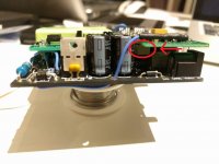
I just wanted to share with you my latest O2 upgrade with agdr's excellent booster board.
This time it is my battery powered low power version O2 that gets boosted up!
As I wanted to keep things as low power as possible, I went for OPA140s, which are agdr's second choice all things considered, an first option if lower current draw is a priority.
Anyways, 'nuff chitchat, let the pics do the talking!
The board was sent to me already populated by agdr, except for the opamps. That turned out to be my first surface mount soldering experience. It wasn't too bad, I think...

As you might notice, I removed the LEDs since I won't be making holes on the face plate, and it might save some battery power!
As it was getting crowded with the latch board in place, I decided to route and solder the anti-thump wire underneath the O2's board:


Quit snug, IMHO [emoji41]

Thanks again agdr for the quality of your work! [emoji122]
I just wanted to share with you my latest O2 upgrade with agdr's excellent booster board.
This time it is my battery powered low power version O2 that gets boosted up!
As I wanted to keep things as low power as possible, I went for OPA140s, which are agdr's second choice all things considered, an first option if lower current draw is a priority.
Anyways, 'nuff chitchat, let the pics do the talking!
The board was sent to me already populated by agdr, except for the opamps. That turned out to be my first surface mount soldering experience. It wasn't too bad, I think...
As you might notice, I removed the LEDs since I won't be making holes on the face plate, and it might save some battery power!
As it was getting crowded with the latch board in place, I decided to route and solder the anti-thump wire underneath the O2's board:
Quit snug, IMHO [emoji41]
Thanks again agdr for the quality of your work! [emoji122]
CHiroshi - thank you for posting those nice pictures!
I like your idea of routing the relay sense wire through the O2 board hole and underneath. Looks great. For anyone out there looking at the Booster Board the first time, I've circled the headphone relay in CHiroshi's photo, below. I have it upside down underneath the
Booster Board to fit in between the stuff on NwAvGuy's O2 board. 🙂
Excellent soldering work on those op-amps! The O2+Booster Board does make quite a boxful, taking full advantage of the vertical space. 😎
Enjoy! 🙂
Attachments
Last edited:
Yes, those holes come in handy when adding stuff to the O2! You probably noticed that I first soldered the resistor sort of straight, but it was a tight fit with the surface components when closing the case. In the last pic you can see how I corrected that by having the resistor in the same "direction" as you would if soldering the wire the usual way.
Skickat från min Nexus 5X via Tapatalk
Skickat från min Nexus 5X via Tapatalk
- Home
- Amplifiers
- Headphone Systems
- O2 headamp output booster PCB