Thanks Vunce, that schematic was the only one I could find, so I will cross reference it with your Mouser Project list and the other BOM's that have been posted by other members.
It’s great to see interest in the ABBB amp coming back. I had another order come in today. Can’t wait to finish mine up.
Very interesting project - any one point me to the original design thread for this? I've searched for ABBB but they seem to refer to other amps.
Thanks
Thanks
The ABBB is a combination of the Alpha 20 (Big Boy 52w version) with the SLB PSU.
Aksa Lender P-mos Hybrid Aleph (ALPHA) Class A Amp GB
The SLB (Smooth Like Butter) Active Rect/CRC/Cap Mx Class A Power Supply GB
Plus a bonus SSR DC protect circuit thrown in for good measure. So it’s a complete amp minus power transformer and heatsinks.
Ready-to-Run (RTR) SSR DC Speaker Protection and Delay GB
We tried to keep as much of the parts through hole as possible for DIY friendly construction.
XRK971 - exactly what I was looking for, many thanks.
Plenty of reading to do. I'm mid-build (for many years) on a KSA50 that I rescued, I have most of the original Krell hardware, case, heatsinks, trafos etc, but it doesn't stop me gathering parts for the next project ;-)
Still need DC protect to save the speakers if it decides to go nuclear again.
Plenty of reading to do. I'm mid-build (for many years) on a KSA50 that I rescued, I have most of the original Krell hardware, case, heatsinks, trafos etc, but it doesn't stop me gathering parts for the next project ;-)
Still need DC protect to save the speakers if it decides to go nuclear again.
Last edited:
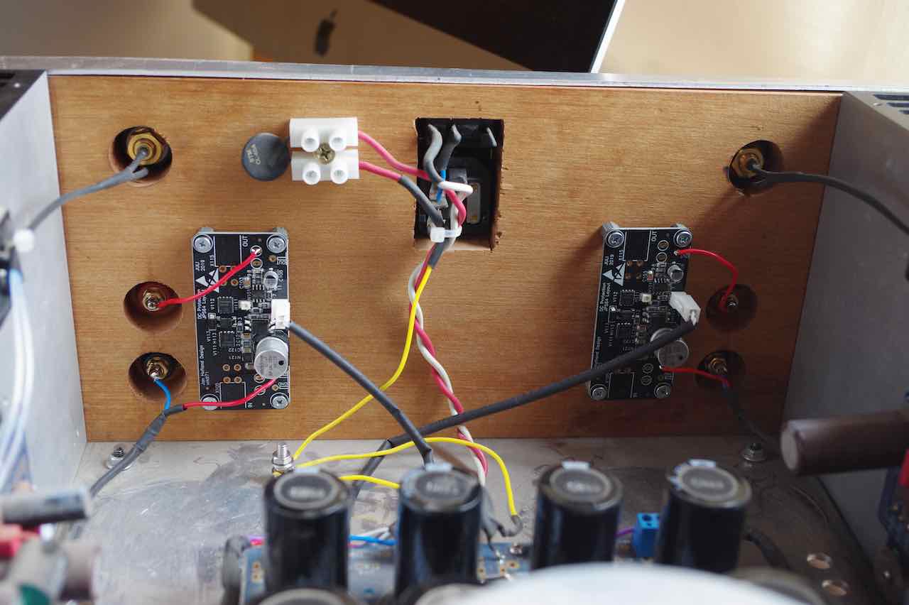
Those DC protect boards have saved my speakers once already and in doing so, paid for themselves.
You can see them here in Wtl's Alpha 20 amp. He said "seems too easy!" to install.
You can see them here in Wtl's Alpha 20 amp. He said "seems too easy!" to install.
A 2 x 0-32 transformer is harder to get in the UK than 0-30 or 0-35, basically twice the price - the number of suppliers for 0-32 is very small.
Presumably 0-30 sacrifices a small amount of output power and 0-35 results in an even larger thermal problem to manage.
Is the 0-30 one a reasonable choice?
Presumably 0-30 sacrifices a small amount of output power and 0-35 results in an even larger thermal problem to manage.
Is the 0-30 one a reasonable choice?
Is the 0-30 one a reasonable choice?
30v secondaries will not be a problem. 🙂
ABBB H2O Build Update
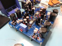
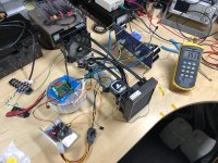
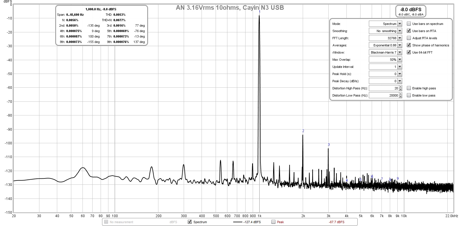
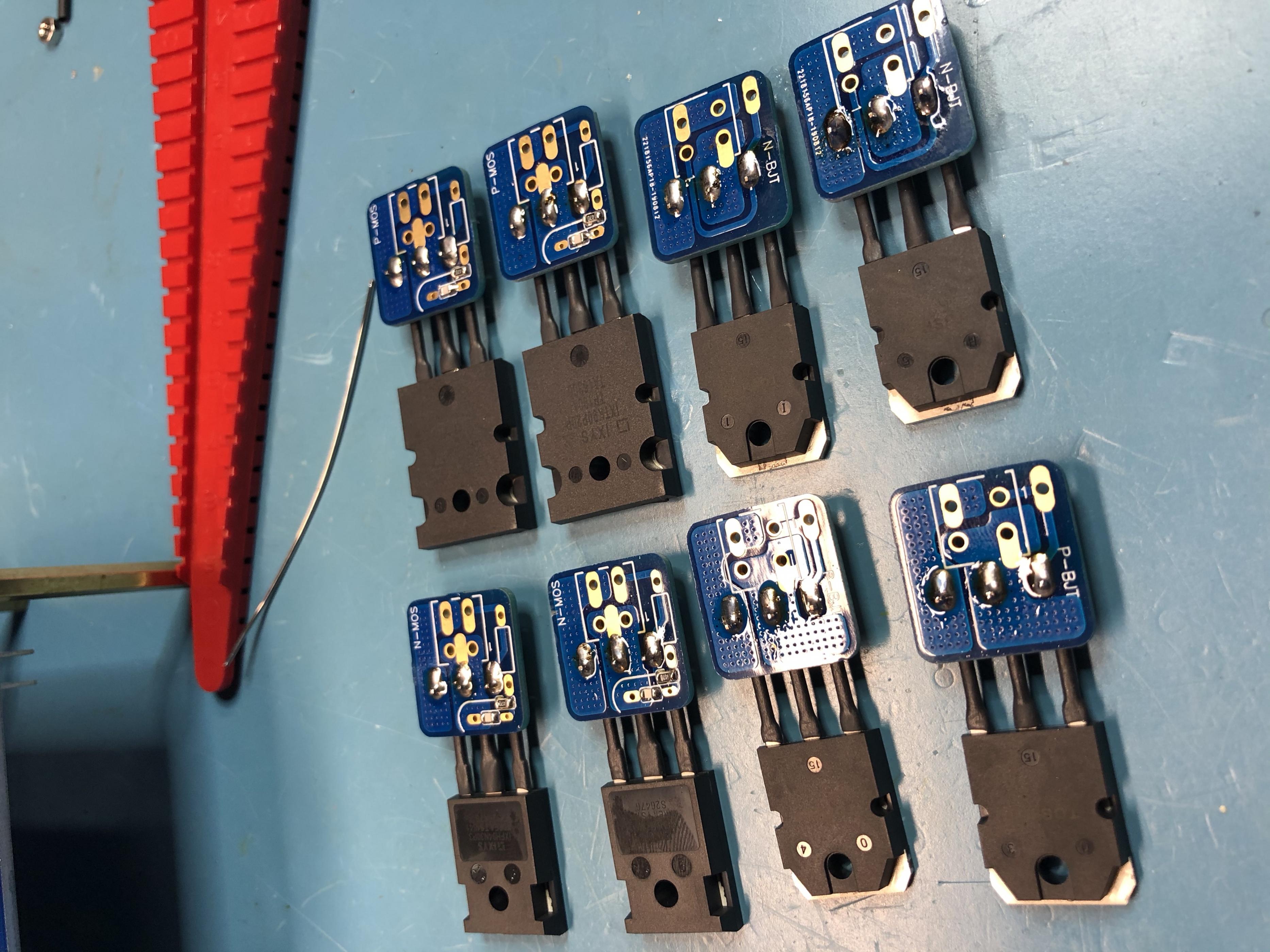
I've finally gotten one ABBB channel soldered, connected, temporarily mounted for my water cooled ABBB build. The MOSFETs and BJTs are mounted on a 2x1/4" aluminum bar using the mounting hardware included with the Corsair H60 all in one liquid coolers. Currently, I am using some SilPad to electrically insulate and thermally couple them to the copper water block. I have some Keratherm I'll use in the final build.
Some build notes:
- If you are mounting both the MOSFETs and BJTs on the same sink using a bar across the top, you'll need to add a 0.02" shim for the BJT to get them level for mounting
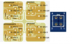
- I proceeded (overly?) cautiously in wiring the connections / orientations between the MiniFit and breakout boards, avoiding any assumptions during wiring. To help wrap my mind around this, I annotated a picture of the breakout boards from the schematic and PCB layout. The pin numbering of the MiniFit connectors was not immediately obvious at first glance and the diagram helped clarify this during the build.
- Be cautious as you place components, there are a few resistors that are a tight fit and they need to be carefully placed to ensure they overlap in a meaningful and safe manner 🙂
- Don't forget to order extra KSA992FBUs (V101, V105) for matching, I'll be desoldering my current pairs and ordering some for matching shortly.
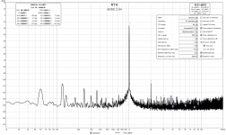
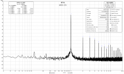
That said, on to the measurements. I've completed the soldering of both channels, but have only hooked one up for testing. My measurements in REW are attached, but here is the breakdown for my tested channel:
- 2.9V@8, ~1W: 0.0033% THD
- 9V@8, ~10W: 0.011% THD
- 22V@8, ~60W: 0.089% THD (60W!!! beyond this we skyrocket into clipping)
Bias: 2.9A (voltage measured across R147 / 0.22)
Antek AN-6432 32V transformer and cap-mx adjusted to be the minimum matching voltages possible given the adjustment range:
- Negative rail: -42.9V before BJT (X231 pin 2/4), -39.4V after (X231 pin 3)
- Positive rail: 42.8V before BJT (X211 pin 3), 39.4V after (X211 pin 2/4)
- AC ripple: about 120mV before BJT, down to 2.5-3mV after
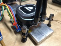
Temperature was measured and monitored during testing on the copper water block. It remained fairly constant at idle after warm up and then with load. Overall, depending on the radiator fan speed, temperature remained between 30 and 40C. I think I'll be able to run the fans under 1000rpm and will likely be upgrading to Noctua fans. Interestingly, or maybe not, the aluminum bar that the back side of the transistors are mounted on is running consistently 10C hotter than the actual cooper block with the dies. This won't be a problem, but when I case it up, I'll likely add a large fan on the top of the chassis to help extract this hot air and the air pulled in to cool the radiators.
Phew... all in all, I think things are running as I had hoped!
One question about my measurement results. Given that this is a test setup, should I be concerned about the 60hz and 120hz humps I'm seeing? Is this indicative of a ground loop in my test setup? (I am using an ESI Juli@ PCI sound card). For testing I have the PE chassis ground connected to the mains ground. I quickly tested without the water cooling power connected (no fans or pumps) and saw no change and also tested with PE disconnected with no change. I figure this is something that will probably iron itself out in a real build, but want to catch anything early so I can plan ahead. Any other concerns in these results that I should look into?
My next steps:
- Test second channel to ensure consistent results and no explosions
- Build soft start
- Order some KSA992FBU's for matching and replace
- Look into a super cap circuit to keep the fans and pumps running for a few minutes after power down to allow everything to cool off. Currently temps ramp up 5-10C before stabilizing and cooling and I would like to avoid this. I'm thinking of throwing something like 1/2/4PCS 15V-1F Farad Capacitor Single Row Electrical Component Super Capacitor | eBay on my 12v rail and see how long it'll keep everything running.
- Start formalizing some case plans, the general layout should follow what is shown in the testing pics. The transformer and ABBB will be mounted vertically and the case will likely be constructed using 20x20 or 30x30 extrusions 😀
Thanks everyone for their hard work on this project, hopefully the notes from my build will help other people as they progress in their own!
- Greg
I've finally gotten one ABBB channel soldered, connected, temporarily mounted for my water cooled ABBB build. The MOSFETs and BJTs are mounted on a 2x1/4" aluminum bar using the mounting hardware included with the Corsair H60 all in one liquid coolers. Currently, I am using some SilPad to electrically insulate and thermally couple them to the copper water block. I have some Keratherm I'll use in the final build.
Some build notes:
- If you are mounting both the MOSFETs and BJTs on the same sink using a bar across the top, you'll need to add a 0.02" shim for the BJT to get them level for mounting
- I proceeded (overly?) cautiously in wiring the connections / orientations between the MiniFit and breakout boards, avoiding any assumptions during wiring. To help wrap my mind around this, I annotated a picture of the breakout boards from the schematic and PCB layout. The pin numbering of the MiniFit connectors was not immediately obvious at first glance and the diagram helped clarify this during the build.
- Be cautious as you place components, there are a few resistors that are a tight fit and they need to be carefully placed to ensure they overlap in a meaningful and safe manner 🙂
- Don't forget to order extra KSA992FBUs (V101, V105) for matching, I'll be desoldering my current pairs and ordering some for matching shortly.
That said, on to the measurements. I've completed the soldering of both channels, but have only hooked one up for testing. My measurements in REW are attached, but here is the breakdown for my tested channel:
- 2.9V@8, ~1W: 0.0033% THD
- 9V@8, ~10W: 0.011% THD
- 22V@8, ~60W: 0.089% THD (60W!!! beyond this we skyrocket into clipping)
Bias: 2.9A (voltage measured across R147 / 0.22)
Antek AN-6432 32V transformer and cap-mx adjusted to be the minimum matching voltages possible given the adjustment range:
- Negative rail: -42.9V before BJT (X231 pin 2/4), -39.4V after (X231 pin 3)
- Positive rail: 42.8V before BJT (X211 pin 3), 39.4V after (X211 pin 2/4)
- AC ripple: about 120mV before BJT, down to 2.5-3mV after
Temperature was measured and monitored during testing on the copper water block. It remained fairly constant at idle after warm up and then with load. Overall, depending on the radiator fan speed, temperature remained between 30 and 40C. I think I'll be able to run the fans under 1000rpm and will likely be upgrading to Noctua fans. Interestingly, or maybe not, the aluminum bar that the back side of the transistors are mounted on is running consistently 10C hotter than the actual cooper block with the dies. This won't be a problem, but when I case it up, I'll likely add a large fan on the top of the chassis to help extract this hot air and the air pulled in to cool the radiators.
Phew... all in all, I think things are running as I had hoped!
One question about my measurement results. Given that this is a test setup, should I be concerned about the 60hz and 120hz humps I'm seeing? Is this indicative of a ground loop in my test setup? (I am using an ESI Juli@ PCI sound card). For testing I have the PE chassis ground connected to the mains ground. I quickly tested without the water cooling power connected (no fans or pumps) and saw no change and also tested with PE disconnected with no change. I figure this is something that will probably iron itself out in a real build, but want to catch anything early so I can plan ahead. Any other concerns in these results that I should look into?
My next steps:
- Test second channel to ensure consistent results and no explosions
- Build soft start
- Order some KSA992FBU's for matching and replace
- Look into a super cap circuit to keep the fans and pumps running for a few minutes after power down to allow everything to cool off. Currently temps ramp up 5-10C before stabilizing and cooling and I would like to avoid this. I'm thinking of throwing something like 1/2/4PCS 15V-1F Farad Capacitor Single Row Electrical Component Super Capacitor | eBay on my 12v rail and see how long it'll keep everything running.
- Start formalizing some case plans, the general layout should follow what is shown in the testing pics. The transformer and ABBB will be mounted vertically and the case will likely be constructed using 20x20 or 30x30 extrusions 😀
Thanks everyone for their hard work on this project, hopefully the notes from my build will help other people as they progress in their own!
- Greg
Attachments
-
 0-abbb-boards.jpg977.7 KB · Views: 476
 -
 1-abbb-breakout.jpg893.4 KB · Views: 714
 -
 2-abbb-leads.jpg904.2 KB · Views: 439
 -
 3-abbb-mount.jpg700.3 KB · Views: 3,057
 -
 4-abbb-testing.jpg1,005.1 KB · Views: 313
 -
 abbb-flying-lead-pcb.png368.8 KB · Views: 314
 -
 rew-abbb-2-9v.png112.7 KB · Views: 225
 -
 rew-abbb-9v.png110.8 KB · Views: 238
 -
 rew-abbb-22v.png107.9 KB · Views: 3,682
Last edited:
Gtose,
This is superb work and you are true pioneer! Congrats on the very first water cooled ABBB! (or maybe Alpha for that matter?)
The measurements are excellent and the 60Hz/120Hz peaks you are seeing are consistent with what I have been seeing with SLB. I am getting about -115dB for my mains hum peaks on the Alpha Nirvana. This is running 3.4A so in similar ballpark as yours. You might be able to clean it up a bit more by running a ground wire from the aluminum clamp bar to chassis ground star hub. Also, once you put this in a metal box, it helps. I have also found that an NTC like 8D-20 on the trafo primary to serve as a soft-start, and it also seems to reduce the 60Hz peak. Be carfeful though, it runs hot enough to burn if you touch it.
Thank you so much for taking this project all the way through to the REW measurements! I did not expect the harmonic profile to look this good, nor the THD to be this low (0.003%) at 1w. And to be able to hit 60w! Yaoozaa! 😀
I really like how compact the water cooling setup is! Do you have a link to the particular unit you bought?
Last edited:
Brilliant Gary,
Expert building, and very good appearance.
I hope you love your ABBB for many decades!
Thank you for building it for me and X, makes our day.
Hugh
Expert building, and very good appearance.
I hope you love your ABBB for many decades!
Thank you for building it for me and X, makes our day.
Hugh
Hi Hugh.
I bet you are enjoying the cooler (Class A) weather in Melbourne just now - my ABBB build will now wait till Autumn when the weather here in NSW cools off a bit. I have all I need to build it and it is definitely on my to do list. Will double check and measure all components over the Christmas break. Thanks again for all of these beaut Class A designs (I hope this does not stir a certain member into his usual Class A rants)
Best regards and enjoy Christmas.
Gary..
Hi Greg,
I knew from your early planning that your implementation of the ABBB would be special and you did not disappoint. Awesome liquid cooling setup with some excellent measurements to back it up. I’m looking forward to your next build update 🙂
Cheers,
Vunce
I knew from your early planning that your implementation of the ABBB would be special and you did not disappoint. Awesome liquid cooling setup with some excellent measurements to back it up. I’m looking forward to your next build update 🙂
Cheers,
Vunce
I hope this does not stir a certain member into his usual Class A rants
Gary..
Huh....you mean me ?? 🙁🙄😱😀
No, I will not rant: this is a ~35 watt @ 8 ohm class A amplifier.
Just keep it cool and healthy with over 200 watt dissipation.
You will listening class A for 99.9 % of the time 🙂
A beautiful sight. Big fat IXYS MOSFETs that never shut off all the way to clipping.
I just noticed that Gtose mounted the Minfit Molex underneath the PCB on the bottom side. Interesting! You really need to manually check the pinouts on that one!
I just noticed that Gtose mounted the Minfit Molex underneath the PCB on the bottom side. Interesting! You really need to manually check the pinouts on that one!
Last edited:
Thanks all of the kind words and motivation to test the other channel 🙂 X, also thank you for the clarification and comparison on the mains bumps. I'll test grounding the mounting bar and see if it has an impact.
I just tested the second channel and it has a little lower rails voltages, so reduced the cap-mx drop a hair to get the voltages close for each channel. Test results were nearly identical. I still need to test the other set of transistors.
I am using a Corsair H60 (2018 version): https://www.corsair.com/us/en/Categ...2018)-120mm-Liquid-CPU-Cooler/p/CW-9060036-WW
I'm waiting to see if the price drops before buying the remaining 2 for the second channel.
Yeah, hence the annotations on the breakout board and MiniFit connectors 🙂. I will be mounting the ABBB vertically and will have the power wiring and transistor wiring going on the bottom side through cutouts on the mounting plate. This will allow all power wiring to head one direction and all I/O to head the other (very close at the back of the amp). The transformer will be mounted vertically at the very front of the amp on the opposite side of the transistors / watercooling to get it as far away from the ABBB as possible. In my initial testing (shown in the attached pic) I had a lot more high frequency hash when the transformer was mounted near the ABBB.
- Greg
I just tested the second channel and it has a little lower rails voltages, so reduced the cap-mx drop a hair to get the voltages close for each channel. Test results were nearly identical. I still need to test the other set of transistors.
I really like how compact the water cooling setup is! Do you have a link to the particular unit you bought?
I am using a Corsair H60 (2018 version): https://www.corsair.com/us/en/Categ...2018)-120mm-Liquid-CPU-Cooler/p/CW-9060036-WW
I'm waiting to see if the price drops before buying the remaining 2 for the second channel.
I just noticed that Gtose mounted the Minfit Molex underneath the PCB on the bottom side. Interesting! You really need to manually check the pinouts on that one!
Yeah, hence the annotations on the breakout board and MiniFit connectors 🙂. I will be mounting the ABBB vertically and will have the power wiring and transistor wiring going on the bottom side through cutouts on the mounting plate. This will allow all power wiring to head one direction and all I/O to head the other (very close at the back of the amp). The transformer will be mounted vertically at the very front of the amp on the opposite side of the transistors / watercooling to get it as far away from the ABBB as possible. In my initial testing (shown in the attached pic) I had a lot more high frequency hash when the transformer was mounted near the ABBB.
- Greg
Attachments
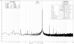
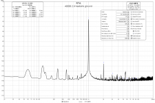
Thanks to X's recommendation, I successfully reduced the 60hz by grounding the heatsink bar to PE/chassis ground. 60hz in the RTA went down 5db and overall noise went from 0.0066% to 0.0056%. Attached is the new spectrum at 2.9V/~1w. I can't imagine how clean it'll look with proper wiring and placement!
I also got some Noctua A12x25 fans for the radiators, they are running quieter than the water cooling pumps at 1000rpm and keeping temps around 35c. So far, I don't have any concerns about the sound levels even for a quiet listening room. I'm going to try to get the 2 channels moved upstairs sometime this week to the listening room / office to try them out 😀
- Greg
Attachments
Nice result Gary. I once had an amp with massive hum and before I knew better, tolerated it for years, until I realized one day that I forgot to ground it. The hum absolutely vanished to inaudible. I think the heatsink acts like a big 60Hz EMI antenna and couples into the MOSFETs via capacitance at the insulator.
- Home
- Group Buys
- The Alpha Big Boy with Buttah (ABBB) 52w Class A Amp GB