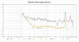
That is much clearer 🙂 Do you know what the SPL level and distance was for the measurement? Without that information it is pretty hard to compare against the plots I posted, my SPL levels as shown in the graphs are correct and calibrated, distance was about 2.7m in the in room one and probably 2m for the outdoor, can't remember.I've selected a volume level that produced the least distortion for the non-horn speaker and then level matched the horn speaker's to the non-horn. This ensured I wasn't stressing the non-horn speaker which would invalidate the comparison. So the horn is -60dB from the fundamental (0.10%) while the non-horn is -48dB (0.80%), looking at 1kHz region.
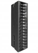
An intriguing picture of a line array horn was posted. What can you tell us about that horn's measured or expected or simulated performance?
More information would be very welcome 🙂
I am interested to see if the line array waveguide gets built and tested and the real life effects of the phase plug. Seems like it will be quite the construction project if it would be formed from stacked CNC cut pieces.
It does seem to be a good option for crumboo given the placement constraints in his room.
Yes, more info would be welcome. Building such horn is a big investment, so I need to be pretty sure that it works 🙂
I'm a bit worried about the the dip at 5 kHz also - can anything be done about it? I'd like to be able to do some simulations to get a clearer view on how the horn + phase plug works. I do have access to Comsol through work, but not the skills (yet).
I'm a bit worried about the the dip at 5 kHz also - can anything be done about it? I'd like to be able to do some simulations to get a clearer view on how the horn + phase plug works. I do have access to Comsol through work, but not the skills (yet).
A potentially cheaper way to make something like that waveguide would be to build it like an aeroplane wing, have a few of the shaped pieces as ribs and wrap it in thin ply. The void could be filled with whatever you like, halair's expoxy crete might work well and be heavy enough to be free standing.
Here's a comparison between the horn vs non-horn. The left column of measurements is the non-horn single driver... right is the E-250 horn with four SS 10F drivers. There is only one phase plug in between the two middle drivers. There is 0.10% distortion through the midrange with the horn... is this good performance compared to non-horn multiple driver line array? Please share if you've measured your line array. My mic distance was one meter.
Are the basic horn (profile) and the slot width (1.7") of the E-250 similar to the horn of your line array?
FWIW, according to Bob McCarthy:
"If time offset is small, such as 0.1 ms, the initial coupling range will extend all the way to 3 kHz before falling into a hole at 5 kHz and back up again at 10 kHz."
I wonder if the dip would be there with the 4 drivers in a 'naked' array (without the horn).
Last edited:
Seeburg's GL 16 for comparison. Some issues >4k, despite the use of 1" dome tweeters.
Attachments

Last edited:
Are the basic horn (profile) and the slot width (1.7") of the E-250 similar to the horn of your line array?
FWIW, according to Bob McCarthy:
"If time offset is small, such as 0.1 ms, the initial coupling range will extend all the way to 3 kHz before falling into a hole at 5 kHz and back up again at 10 kHz."
I wonder if the dip would be there with the 4 drivers in a 'naked' array (without the horn).
That's quite easy to test by measuring the 4 driver horn array from a greater distance and see if the dip moves accordingly. You'll change the difference in distance of each driver to the microphone that way.
Joseph posted offaxis plots of the horn and 4 driver array in the thread before, that 5K dip is present in all of them.

I had a look at Joseph's blog page on the setup
ScanSpeak/THIEL 10F/8424G02 4" Fiberglass Midrange in E-250 Horn – Joseph Crowe and I found an answer to the level question, measurement was taken at 80dB, distance does not seem to be quite as far but the picture could be deceiving.
On that same page is a distortion graph that shows a big spike at the same frequency as the dip

The most likely causes from looking at the layout to me are either a cancellation from the front chamber created from the horn overlapping the drivers or the single divider between two drivers. It does look as if the horn was designed for the Neo ribbon for which it works very well. A phase plug per driver would most likely bring improvements. A full line rather than a truncated one would also help.
I had a look at Joseph's blog page on the setup
ScanSpeak/THIEL 10F/8424G02 4" Fiberglass Midrange in E-250 Horn – Joseph Crowe and I found an answer to the level question, measurement was taken at 80dB, distance does not seem to be quite as far but the picture could be deceiving.
On that same page is a distortion graph that shows a big spike at the same frequency as the dip
The most likely causes from looking at the layout to me are either a cancellation from the front chamber created from the horn overlapping the drivers or the single divider between two drivers. It does look as if the horn was designed for the Neo ribbon for which it works very well. A phase plug per driver would most likely bring improvements. A full line rather than a truncated one would also help.
Attachments
The most likely causes from looking at the layout to me are either a cancellation from the front chamber created from the horn overlapping the drivers or the single divider between two drivers. It does look as if the horn was designed for the Neo ribbon for which it works very well. A phase plug per driver would most likely bring improvements. A full line rather than a truncated one would also help.
A 4 driver array should work (without dip) as well IMHO.
Your assessment regarding the cancellation and the single divider makes sense.
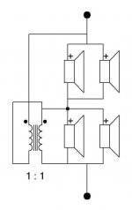
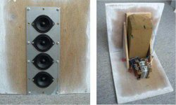
A fellow Dutchmen built a small dipole array with 4x VISATON FRS 5X and used Oasis (floral foam) as 'rear chamber'.
The transformer was used to match the impedance between the drivers.
Attachments
Last edited:
I wasn't very clear in what I wrote, the 5K dip appears to be a reflection null and not directly related to the 4 drivers. In the second part I was trying to say that a floor to ceiling line of anything should perform better than a truncated line. Line array theory and practical measurements bear that out.A 4 driver array should work (without dip) as well IMHO.
Your assessment regarding the cancellation and the single divider makes sense.
A fellow Dutchmen built a small dipole array with 4x VISATON FRS 5X and used Oasis (floral foam) as 'rear chamber'.
The transformer was used to match the impedance between the drivers.
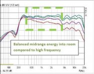
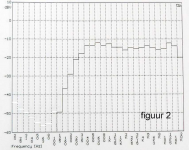
I hope this doesn't sound dismissive but that type of measurement tells me very little about the speaker 🙂In room TrueRTA measurement of the same dipole array, 1/12 oct.
I wasn't very clear in what I wrote, the 5K dip appears to be a reflection null and not directly related to the 4 drivers.
That's what I understood, and my sentences were 2 separate comments.
In the second part I was trying to say that a floor to ceiling line of anything should perform better than a truncated line. Line array theory and practical measurements bear that out.
No doubt about this and it's what this thread is all about. Sometime in the future I may build a floor-ceiling array, but I'd prefer to start with a smaller array, using 4, or 8 drivers to get a taste of the full range drivers (' sound).
I hope this doesn't sound dismissive but that type of measurement tells me very little about the speaker 🙂
No it doesn't.
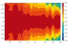
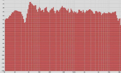
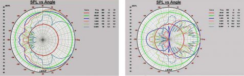
Few measurements of these small arrays are provided... however, I forgot about the radiation plots. Obviously, left are the horizontals and right the verticals

Attachments
Last edited:
Seems like I was clear enough the first time 😉That's what I understood, and my sentences were 2 separate comments.
I don't think a small array is a stepping stone along the way to a full line, they are quite different. I see the attraction in a smaller, easier, cheaper build but I have seen nothing that makes me think they are worth trying.No doubt about this and it's what this thread is all about. Sometime in the future I may build a floor-ceiling array, but I'd prefer to start with a smaller array, using 4, or 8 drivers to get a taste of the full range drivers (' sound).
Those are better but still not many data points, most of the small arrays seem to be built by people who put no value on measuring anything.No it doesn't.
Few measurements of these small arrays are provided... however, I forgot about the radiation plots. Obviously, left are the horizontals and right the verticals
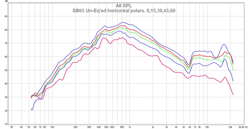
The dip, that is present on all off-axis angles reminds me of the Bookshelf Multi-Way Point-Source thread.
Here's a smaller SB Acoustics SB65WBAC25-4 fullrange driver on an 18 sound waveguide:
https://www.diyaudio.com/forums/multi-way/285030-bookshelf-multi-source-horn-19.html#post4581936
And after EQ:
https://www.diyaudio.com/forums/multi-way/285030-bookshelf-multi-source-horn-20.html#post4582003
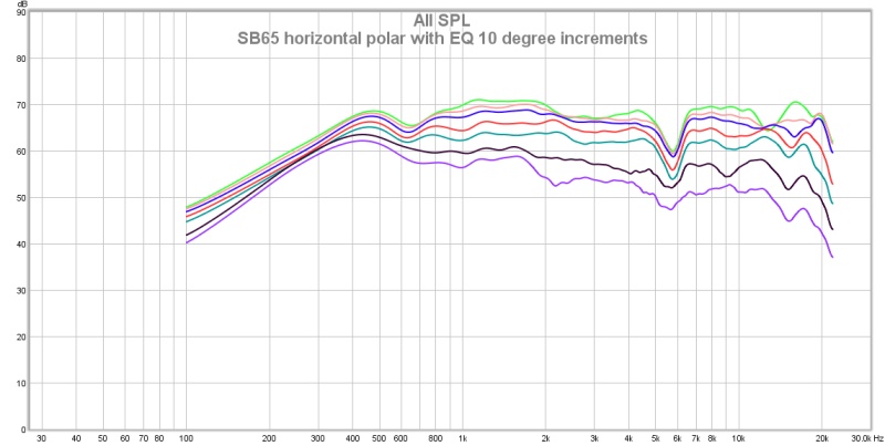
He was able to get it to look like this:
https://www.diyaudio.com/forums/multi-way/285030-bookshelf-multi-source-horn-26.html#post4583417

By reworking the throat area of the horn and using some other tricks. I think a similar recipe might work here.
Fluid, be prepared for a déjà vu 😀
Incorporate that technique in a full floor to ceiling array with waveguide and you'll probably get magic 😀.
If only I could get away with that through my WAF filter here at home, I would have done it already... It is why I saved pic's like this:

Adjust the scale to fit the TC9, lose the central horn and rework the throat to avoid the nasties there... much like the drawings from Joseph,
but with a bit of extra attention to the throat area.
Here's a smaller SB Acoustics SB65WBAC25-4 fullrange driver on an 18 sound waveguide:
https://www.diyaudio.com/forums/multi-way/285030-bookshelf-multi-source-horn-19.html#post4581936
And after EQ:
https://www.diyaudio.com/forums/multi-way/285030-bookshelf-multi-source-horn-20.html#post4582003
He was able to get it to look like this:
https://www.diyaudio.com/forums/multi-way/285030-bookshelf-multi-source-horn-26.html#post4583417
By reworking the throat area of the horn and using some other tricks. I think a similar recipe might work here.
Fluid, be prepared for a déjà vu 😀
Really nice result how did you do it? 😉
OK, so a LOT of polishing, I tried various spacers - settled on some acoustic damping wool I have used in the past on baffles to reduce baffle diffraction.
I sloped the throat a little bit more, then lined the space between the surround, bezel and throat with a ring of it.
It has completely removed the cancellation.
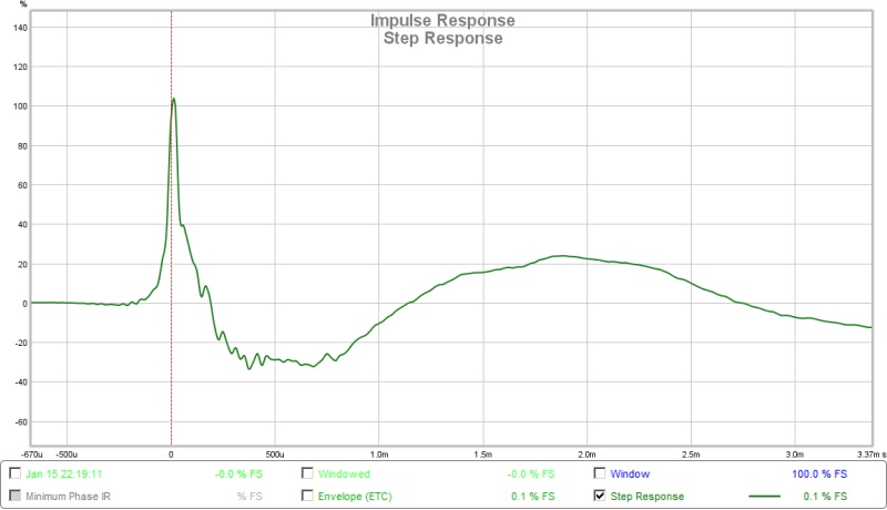
Here is the step.
Incorporate that technique in a full floor to ceiling array with waveguide and you'll probably get magic 😀.
If only I could get away with that through my WAF filter here at home, I would have done it already... It is why I saved pic's like this:
Adjust the scale to fit the TC9, lose the central horn and rework the throat to avoid the nasties there... much like the drawings from Joseph,
but with a bit of extra attention to the throat area.
Attachments

Last edited:
that driver to throat transition for a floor to ceiling horn is critical
it affects the response two ways - the reflection/dip problem shown here but any restriction to narrow the source also creates a throat chamber that acts as an acoustic low pass filter that adds to the line arrays inherent roll off.
it affects the response two ways - the reflection/dip problem shown here but any restriction to narrow the source also creates a throat chamber that acts as an acoustic low pass filter that adds to the line arrays inherent roll off.
Yes, I know. I've got half finished drawings that do that on my computer but too many questions to answer before I finish them. I'm starting with AxiDriver but I think it will take ABEC3 to answer them...
The dip, that is present on all off-axis angles reminds me of the Bookshelf Multi-Way Point-Source thread.
...
That's really interesting - something I should read, thanks!
True, but it does offer an opportunity to use synergy like infusion for the low notes 🙂.
Yes, I know. I've got half finished drawings that do that on my computer but too many questions to answer before I finish them. I'm starting with AxiDriver but I think it will take ABEC3 to answer them...
A interesting idea, and something I like to investigate further. I'd be happy if you guys could elaborate on this a bit more?
The basic idea is to put a line of woofers or mid woofers behind the horn walls feeding sound through holes in those walls so you can offload the fullrange drivers from 200 Hz where their excursion generally begins to rise on down. The CTC between the woofers and the full range drivers will be small enough so you can get a truly seamless crossover and the combination will be perceived as a single line. Dynamics will be improved as will the bass response....
Whether or not those are needed improvements for a subwoofer assisted line of TC9s is debatable, depending on your room and listening level among other things. But the concept does allow the use of smaller drivers with improved treble dispersion that are not as robust as the TC9 in the low end. And it can reduce the overall footprint to include sufficient woofage to reach down to 20 Hz w/o subs. To say nothing of the acoustic and visual dramatic impact of a really powerful truly full range system.
Whether or not those are needed improvements for a subwoofer assisted line of TC9s is debatable, depending on your room and listening level among other things. But the concept does allow the use of smaller drivers with improved treble dispersion that are not as robust as the TC9 in the low end. And it can reduce the overall footprint to include sufficient woofage to reach down to 20 Hz w/o subs. To say nothing of the acoustic and visual dramatic impact of a really powerful truly full range system.
here is an xray view of a rough concept with 1.5" full range drivers and 6.5" woofers. the woofers hug the side of a murphy corner style full range array cabinet and form a 90 degree corner horn. The mouth of the horn needs termination. Nothing sophisticated has been done in the throat....but it shows the basic structure.
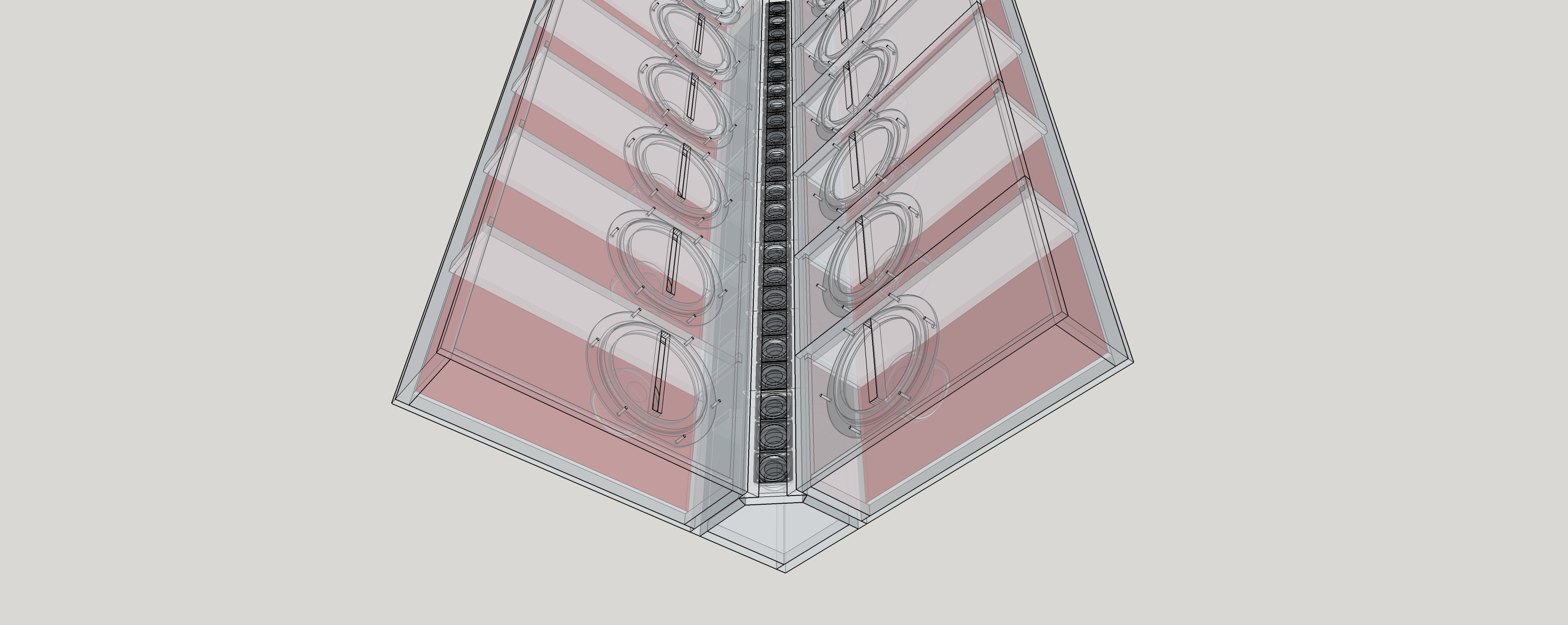
Here is picture of a 60 degree corner horn with a mouth roundover that I'm developing a sim model for primarily because I'm curious as to how much a mouth termination does to cure the ills of a conical horn. I think its too much to ask even a 1.5" driver to fill a 90 degreeH horn. Narrowing the flares to 60 degrees gives more room for the mouth termination and for woofers inside the flares.
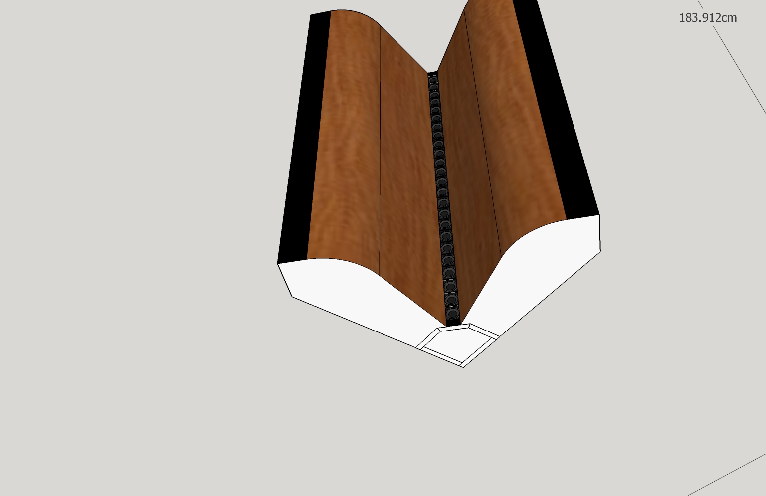
This particular sketch matches the footprint of the bass bin of the corner horn in my signature and is only half height. I could build it to sit on top of that bass bin replacing the Synergy top their now and curing that design's lack of vertical directivity. (this would make for an awesome pair of computer speakers in my home office!) If I were building it to stand alone, I would double the height and continue the round over all the way to meet the back wall. As fluild suggested, I would CNC ribs and skin them with two or 3 levels of 1/8" plwood and then veneer.
Here is picture of a 60 degree corner horn with a mouth roundover that I'm developing a sim model for primarily because I'm curious as to how much a mouth termination does to cure the ills of a conical horn. I think its too much to ask even a 1.5" driver to fill a 90 degreeH horn. Narrowing the flares to 60 degrees gives more room for the mouth termination and for woofers inside the flares.
This particular sketch matches the footprint of the bass bin of the corner horn in my signature and is only half height. I could build it to sit on top of that bass bin replacing the Synergy top their now and curing that design's lack of vertical directivity. (this would make for an awesome pair of computer speakers in my home office!) If I were building it to stand alone, I would double the height and continue the round over all the way to meet the back wall. As fluild suggested, I would CNC ribs and skin them with two or 3 levels of 1/8" plwood and then veneer.
Attachments


- Home
- Loudspeakers
- Full Range
- Another corner line array, 28 TC9FD18