I'd have to agree with nc535 if one would go for such an attempt of combining the Synergy principle with a waveguided array, it would be best to start with a smaller driver at the apex.
The whole idea behind the TC9 arrays, at least in my personal quest was to have it play as much as possible of the entire bandwidth of interest, from the low notes to the higher ones. That doesn't mean I oppose to any helper woofers or tweeters if that improves the total performance. In fact I have done so on the bottom end and will not rule out any further experimentation if I feel like it.
However, once you change the game, other options could/should be considered.
It would be interesting to see simulated performance of an array of TC9's behind a waveguide. To know what to expect at the bottom end.
The first results from that 4 array driver from Joseph with 10F drivers, which are a match to the TC9 size wise do make it interesting to see if we can find ways to avoid that big notch. Just be aware that it will have an effect on the bottom end potential as well.
If we could get it to behave on the waveguide, you could still use the Synergy approach to reinforce that bottom end. However it would make sense to start with smaller drivers when starting from scratch with an idea like that.
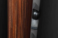
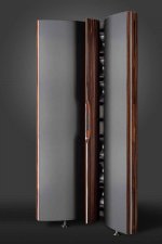
Interesting concept NC535, it somehow reminds me of the Backes & Müller Line 80 and 100.
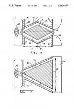
Except those are not full range line arrays. From 800 Hz and up the single Line Radiation Unit (or, in German: Zylinderwellenstrahler) takes over.
The BM 100 is fully compression loaded though.
Except those are not full range line arrays. From 800 Hz and up the single Line Radiation Unit (or, in German: Zylinderwellenstrahler) takes over.
The BM 100 is fully compression loaded though.
Attachments
-
 BMLine 100(1)-1ebc7656.jpg64.9 KB · Views: 294
 -
 BMLine 100(2)-b5b1914c (1).jpg54.8 KB · Views: 298
 -
 K1024_Loft1-1.jpg68.5 KB · Views: 299
 -
 K1024_Loft_front2.jpg80.9 KB · Views: 305
 -
 BM80-(3).jpg46.9 KB · Views: 312
 -
 BM-Prinzipbild-Waveformer-2.jpg63 KB · Views: 134
 -
 BM-Prinzipbild-Waveformer-1.jpg77.2 KB · Views: 157
 -
 BM80_224-web.jpg601.2 KB · Views: 166
 -
 BM-BM-80-15.jpg72.3 KB · Views: 173
 -
 BM Line Radiation Unit_200.jpg97 KB · Views: 170
Last edited:
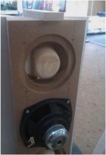
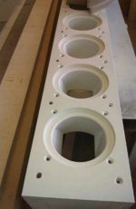
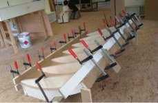
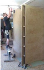
Some mediocre-quality pictures of the construction of the BM Line 100:
Attachments
Last edited:
Interesting concept NC535, it somehow reminds me of the Backes & Müller Line 80 and 100.
Except those are not full range line arrays. From 800 Hz and up the single Line Radiation Unit (or, in German: Zylinderwellenstrahler) takes over.
The BM 100 is fully compression loaded though.
Thanks for the pics, RO. As often they are inspirational. Unfortunately for me the resemblance to my concept is faint and only visual. B&M seem to have mastered the technique of using tweeter/tweeter array as a phase plug for a LF array. I suppose if one can afford a house large enough for those speakers, one can also afford the speakers.
But I want/need speakers that will hug the wall and have minimum footprint. Earlier threads, (Bushmeister's) showed how critical throat treatment is in mating a full range driver to a horn. I think its even more so for a line of them. I may have to fall back to my earlier concept of flanking the corner line array with absorbers and then, if I want a companion bass array, have it play through one of the absorbers.
Thanks for the pics, RO. As often they are inspirational. Unfortunately for me the resemblance to my concept is faint and only visual.
It was only the visual aspect of your concept - especially the horns - that reminded me of the BM line speakers 😉
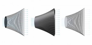
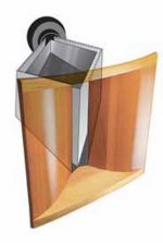
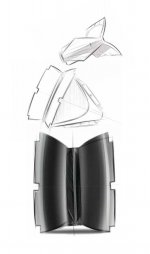
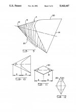
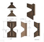
I’m sharing this horn design as well for interest’s sake. This uses six 4” midrange drivers with a single compression driver for 2kHz and above. The hour glass shape reduces the off-axis narrowing effect in the upper treble creating an even power response. There should be very good pattern control in the vertical axis which reduces ceiling and floor reflections. So it does not aspire to full array ideals.
Attachments

An interesting design. May I ask what size CNC router are you using? I plan to build one of the designs from V1Engineering.com. For DIY they should be perfectly fine - I am still not decided on the model and size.
Do you think using XPS boards instead of wood would work as well?
Do you think using XPS boards instead of wood would work as well?
The CNC will require 24” x 36” working area.An interesting design. May I ask what size CNC router are you using? I plan to build one of the designs from V1Engineering.com. For DIY they should be perfectly fine - I am still not decided on the model and size.
Do you think using XPS boards instead of wood would work as well?
Joseph, as you have been working a lot with compression drivers and horn loaded full range units lately, how would you describe the differences between those?
Last edited:
Joseph, as you have been working a lot with compression drivers and horn loaded full range units lately, how would you describe the differences between those?
Yes I do go back and forth between them! That's because I can't make up mind either! They are neck and neck in terms of midrange clarity. I keep finding new drivers that exceed my expectations such as the RCF ND-850 1.4 compression driver, and the Scanspeak 10F/8424 3" midrange. However for high frequencies some small format compression drivers take a healthy lead in terms of sound quality.
Good day to you all!
I've spent some time trying to learn Comsol which I have access to trough work in order to simulate radiation pattern and directivity for the proposed corner line array. I think I start to get a hang of it. I do a very simplistic model of the driver membrane, which vibrates in a pistonic motion at desired frequencies with constant acceleration.
The program open up for lots of possibilities to simulate and optimise the design. Some examples:
Simulated geometry of corner array between wall an book shelf:

Zoomed in to see the outer driver geometry:

Sound pressure level at 2512 Hz:

Radiation pattern normalised to maximum level at a radius of 1.5 meters from the corner:

Directivity plot at 1.5 meter radius from corner:

Lot's of interesting investigations can be done here. The software also includes an optimisation tool, so it is possible to optimise baffle/waveguide geometry with respect to desired output. I will try a number of things here and post my results.
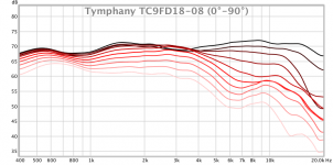
Before continuing: do any of you have directional data for the driver (TC9FD)? I would like to verify the the polar response (as an infinite baffle setup) of the modeled driver geometry so I know I can trust the simulations onward.
I know there are response plots at different angles in the data sheet, but it would be great to have actual numbers/data.
I hope you are all well in these strange times.
Best regards,
Mattias
I've spent some time trying to learn Comsol which I have access to trough work in order to simulate radiation pattern and directivity for the proposed corner line array. I think I start to get a hang of it. I do a very simplistic model of the driver membrane, which vibrates in a pistonic motion at desired frequencies with constant acceleration.
The program open up for lots of possibilities to simulate and optimise the design. Some examples:
Simulated geometry of corner array between wall an book shelf:
Zoomed in to see the outer driver geometry:
Sound pressure level at 2512 Hz:
Radiation pattern normalised to maximum level at a radius of 1.5 meters from the corner:
Directivity plot at 1.5 meter radius from corner:
Lot's of interesting investigations can be done here. The software also includes an optimisation tool, so it is possible to optimise baffle/waveguide geometry with respect to desired output. I will try a number of things here and post my results.
Before continuing: do any of you have directional data for the driver (TC9FD)? I would like to verify the the polar response (as an infinite baffle setup) of the modeled driver geometry so I know I can trust the simulations onward.
I know there are response plots at different angles in the data sheet, but it would be great to have actual numbers/data.
I hope you are all well in these strange times.
Best regards,
Mattias
Welcome to the simulation rat hole!
😀 yes... And I'm closely following your and Wesayso's work on vertical directivity of line arrays as well...
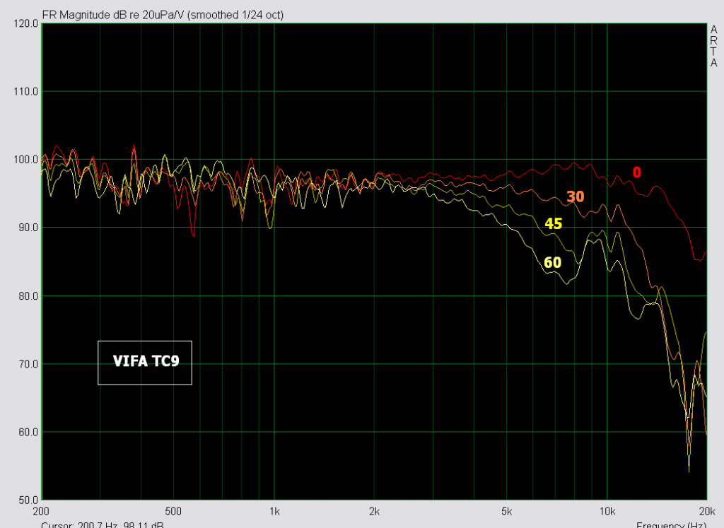
Well then you know you can synthesize directivity for TC9 using Vituix diffraction and SPL trace tools. However, I remember some time ago Art Welter posted a graph of polar measurements of TC9; don't recall where though. Perhaps if you contacted him, he would be willing to share the files behind that graph.
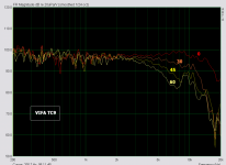
There should be a thread dedicated to the TC9 that has some of these graphs. I've had a lot of those at one time, here's an example:
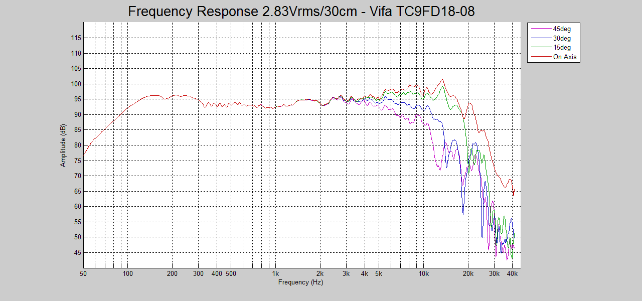
And:
And:
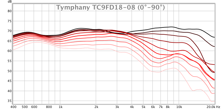
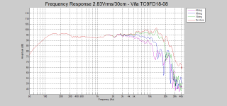
(not of much use this smoothed and without a legend)
And:
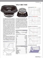
Vifa TC9 - 3" Midrange/Widebander REVIEW/Measurements | DiyMobileAudio.com Car Stereo Forum
I really should have more, somewhere... However due to back mounting mine I've already changed its behaviour. Sadly I did lose the graphs from that! I had a webpage in my links but over time the images have disappeared. Even though it looks like not much could change, the back mounted trivers were more even throughout the 0 to 30 degree window. Reason enough to go for it, motivated even more by the looks that it had.
And:
And:
(not of much use this smoothed and without a legend)
And:
Vifa TC9 - 3" Midrange/Widebander REVIEW/Measurements | DiyMobileAudio.com Car Stereo Forum
I really should have more, somewhere... However due to back mounting mine I've already changed its behaviour. Sadly I did lose the graphs from that! I had a webpage in my links but over time the images have disappeared. Even though it looks like not much could change, the back mounted trivers were more even throughout the 0 to 30 degree window. Reason enough to go for it, motivated even more by the looks that it had.
Attachments
It’s been a while and not much progress I’m afraid. But good things take time!
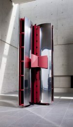
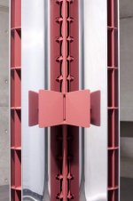
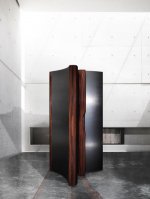
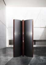
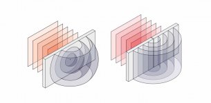
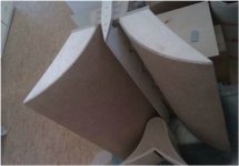
I have a new suggestion for the design in order to avoid to much early reflections in the room. As I have to stick the speakers into the corners of the room and have some difficulties to dampen the first contra lateral wall reflection my idea is to reduce the off axis dispersion with those absorbing half cylinders close to the arrays:


As I said earlier I would like to have a very clear early wave front unobstructed by the room. Any thoughts of this?
Another thing I’ve been thinking about is to use a central tweeter (replacing one or a few of the Vifas). I need something with a quite narrow vertical dispersion and good power handling. Beyma TPL 150 or 200 (with or without the horn) perhaps? What do you guys think about using a central tweeter to handle the top end in this (otherwise full range) array?
I have a new suggestion for the design in order to avoid to much early reflections in the room. As I have to stick the speakers into the corners of the room and have some difficulties to dampen the first contra lateral wall reflection my idea is to reduce the off axis dispersion with those absorbing half cylinders close to the arrays:
As I said earlier I would like to have a very clear early wave front unobstructed by the room. Any thoughts of this?
Another thing I’ve been thinking about is to use a central tweeter (replacing one or a few of the Vifas). I need something with a quite narrow vertical dispersion and good power handling. Beyma TPL 150 or 200 (with or without the horn) perhaps? What do you guys think about using a central tweeter to handle the top end in this (otherwise full range) array?
Unless the cylinders are completely absorptive you will get a lot of very early reflections with a frequency dependent nature. If they are completely absorptive you will lose a lot of spl.
Reducing early reflections can be a good thing but be careful not to throw the baby out with them too 🙂
A central tweeter could be made to work if incorporated as part of the design but it is not that simple. Finding something that has similar directivity to the rest of the line can be tricky and is probably why ribbons and amt's are the easiest to integrate.
When wesayso tests his filter boards the results will be interesting to see and might offer some data on a decision like this. nc535's vituix sims show how difficult it is to get another driver to match the line arrays directivity.
- Home
- Loudspeakers
- Full Range
- Another corner line array, 28 TC9FD18