Is it a Windows setup? Something simple like "listen to this device" could be activated in the mic menu.
Let's see if this picture works:

Also look if other enhancements are accidentally set to on if you're using Windows.
Let's see if this picture works:
Also look if other enhancements are accidentally set to on if you're using Windows.
Last edited:
Is it a Windows setup? Something simple like "listen to this device" could be activated in the mic menu.
Let's see if this picture works:
Also look if other enhancements are accidentally set to on if you're using Windows.
It's a mac. I have an old sound card Terratec Phase 24 connected through firewire to my macbook pro. Mic and preamp from IBF Akustik (not sure that they are around anymore), see attachments.
Mic connected to preamp through RCA cable, and then preamp to sound card input through RCA-1/4" cable. From sound card out to power amp with 1/4" cable (unbalanced).
View attachment emm8.pdf
View attachment MP-1r_manual.pdf
Ah, ok, hopefully some with more experience with Mac will chime in, I have no experience there.
Looks like that company went up into iSEMcon, I've bought my calibrated stuff from them, including phantom power / pré amp. That should be good stuff, did the mic come with a calibration file?
Looks like that company went up into iSEMcon, I've bought my calibrated stuff from them, including phantom power / pré amp. That should be good stuff, did the mic come with a calibration file?
Last edited:
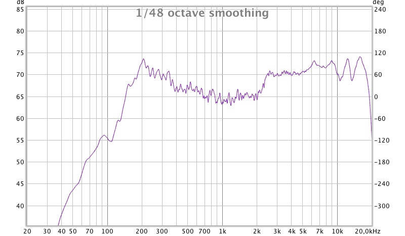
Here's a measurement at about 30 cm, away from objects:
Large time window, 1/48 smoothing:
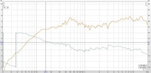
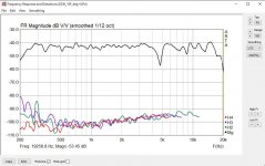
Here is mine a the same scale as yours to try and avoid the optical skewing 1/12 smoothing
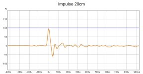
Zoom in on your impulse to have a look your time scale is too long to see what the differences are but you have avoided reflections from further away well enough, a small one at 1.5ms, looks quite messy before though
This is mine and is pretty clean, you can also tell that from the phase above
I would say mainly baffle because yours is quite different to mine, and you are measuring further out, 10cm further might not seem like a lot but it is for baffle effects try it at 20cm centred on the baffle to get a closer match to mine.Any ideas why? 😕
A guess would be simply production differences. They can actually vary quite a bit more than what people normally assume.
The difference in falloff around 200Hz is the most glaring to me, the rest looks like rounding and optical differences between the curves.
These are well made drivers and if handled with care they are very consistent. The plastic frame can warp if too much pressure is applied to the frame from cranking down screws, other than that they are hard to hurt. Unless kids start poking in the dust caps etc. The easiest way to demonstrate it is to put another driver in the same baffle and measure again from the same place. The difference will be small, as wesayso's images have shown they are pretty consistent. I have tried to match the scales above as you are right that there was some optical skewing happening from the different scales.
This sounds and looks like feedback to me. Are you using Java or ASIO drivers in REW and what does the control panel of your interface look like?When I turn the gain up on my mic amp there is noises coming out of the speaker. Even when turned down a bit to avoid clipping the impulse is looking like this:
Can't figure out what the problem is. Tried to change outputs and inputs on the sound card and different settings, but it's stuck like this..😕
Attachments
Last edited:
I tried all sorts of different cables, settings etc. but couldn't get reliable results. I guess that's something wrong with the sound card. Just ordered a UMIK-1 instead so I can bypass the sound card thing. I'll be back! 🙂
I tried all sorts of different cables, settings etc. but couldn't get reliable results. I guess that's something wrong with the sound card. Just ordered a UMIK-1 instead so I can bypass the sound card thing. I'll be back! 🙂
I just received my own UMIK-1. I don't know if it's the best or if I could have done better, but there is some reassurance in knowing there are many different measuring results out there using that mic.
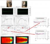
Backing up to the discussion of diffraction slot, I have some simulation results that will be of more interest once the measurement process is conquered.
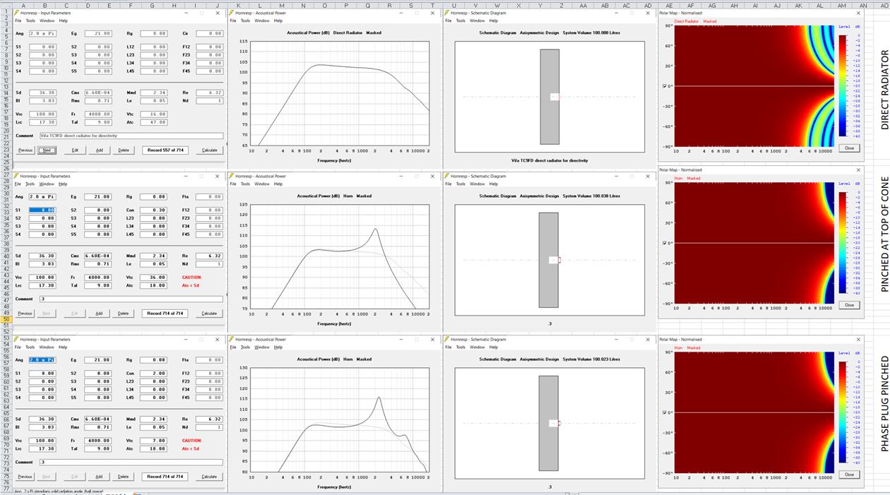
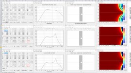
I'm simulating directivity of a flat piston with same Sd as TC9FD. The light grey lines in the frequency responses of the lower 2 rows allow their response to be compared to that of the direct radiator.
The first row of the picture is a direct radiator. It starts narrowing at 5 khz and has full range response only to about =/- 15 degrees.
The second row shows what happens if we place a disc over the surround with a hole only 8 cm2 area, just under half Sd. Beamwidth just about doubles so we get full range response out to about +/- 30 degrees BUT we also create a bandpass chamber whose acoustic low pass filter severely attenuates the HF.
I've estimated the volume of the throat chamber as having average area Sd/2 and a depth of 2cm. I assume below that the phase plug there is a gap of 4mm and same average area.
In the third row, I hypothesie a phase plug that fits over the TC9 and follows its cone with a gap of 4 mm to allow for its excursion. There is still a bandpass effect that can be equalized out but we don't lose any treble.
Such a phase plug is an obvious candidate for 3D printing. Make a solid that fits over the driver using its mounting holes and conforms to the cone surface with a cap. Drill a vertical tunnel on axis of the desired diameter. Make several radial slits at intervals up the tunnel to feed sound in from the sides...
Yes, I know that is easier said than done but also likely much easier to do than a Berstis lense. The benefit should be a wider sweet spot and elimination of the need to point the array directly at the primary LP.
Attachments
The Berstis lens is made to shape the wavefront. In our case we'd like to shape it to act as a line, because shaping it to have a smaller hole would still mean it has the same center to center distance. I do realise that would be a lot to ask from such a phase plug. Making it act like Danley's paraline for a much larger diagram.
Well yes, if it can be done, a lense that formed a line source from a cone would be ideal. But I wanted to put the diffraction slot to bed while improving dispersion. I think the phase plug does that and if you aren't bothered by combing that should be enough.
The Berstis lense has potential though. Think of a number of equal length straws stood up on the one. Then start wrapping the outer straws around the inner, the further out, the tighter the wrap - to end up with a spherical cap at the ends. But that process produces a point source. I don't see an equally simple way to get to a line but I haven't really tried yet either. Maybe there is a complex wrapping/folding/corner turning process that gets there waiting to be discovered.
The Berstis lense has potential though. Think of a number of equal length straws stood up on the one. Then start wrapping the outer straws around the inner, the further out, the tighter the wrap - to end up with a spherical cap at the ends. But that process produces a point source. I don't see an equally simple way to get to a line but I haven't really tried yet either. Maybe there is a complex wrapping/folding/corner turning process that gets there waiting to be discovered.
In all honesty, things are never that simple, changing the off axis response would also influence the on axis comb sum, as more interaction from all drivers due to a wider dispersion would certainly have some influence there too.
Though for the record I would add never having had a problem with the current dispersion pattern.
I didn't toe in my arrays to be on axis, but they sum slightly behind the listening position. So the sweet spot measurements are off axis measurements 😉.
The coverage over my entire listening area is quite even. I would have loved to have them in to cross slightly in front of me but for pure optical reasons that was out of the question. I am well within the 15 degree window (at either side of the array) along the full couch area and absorb (most of) the wider pattern on the left side and even the spray from the right side hitting the left wall. The other side is open in my room, but the damping panels are there for that reason, to even out the response bouncing back to the listening spot. Verified with measurements to have an even room response. The ambient channels help to further achieve that.
Measurements along the listening area of interest have satisfied my curiosity about the pattern control. Toe-in or out is useful to play with though. I've done my share of that before settling on my final array position.
Last edited:
I agree re' dispersion and the width of the listening window. Still wider dispersion is better. It gives more seating flexibility and a better power response. Does it merit wholesale changes or the development and printing of 50 lenses/phase plugs? Probably not but its fun thinking about.
Here's a comparison that illustrates what I'm referring to. I've highlighted the midrange off-axis response and how a front horn drastically alters the power response into the room which has a significant effect on the perceived tonal balance. I should note that the 10F isn't much different than a regular dome tweeter's off-axis characteristics.
Each horn has four drivers. The rear chamber is reflex tuned just below the cutoff frequency of the horn. This controls diaphragm movement outside the horn’s pass band. There’s a 50% reduction in %THD when using the rear chamber across the lower midrange.
Subjectively it reproduces some of the best midrange I’ve heard. I’m using it from 250Hz-20Khz.
Don't let a couple sourpusses keep you from posting, Joseph.
More than a few members of this forum are commercially involved in one way or another. I have yet to come across somebody criticizing Tom Danley's invaluable contributions to the diy community, meanwhile promoting his inventions and thus Danley Sound Labs.
In his own way, Joseph presents interesting loudspeaker concepts, shares useful tips as well as his experiences with various drivers and offers CAD drawings for almost nothing. What's not to like?
Joseph's experiments with 4x ScanSpeak/THIEL 10F/8424G02 4" Midrange in his E-250 Horn and his recent horn loaded vertical column array using 28 TC9FD18-08s piqued my interest.
In the past 5 years I have mainly focused on compression drivers for mid/high duties. While some horn-driver combinations sound glorious - depending on the type of music and quality of the recording, there's no escaping my fascination (and preference) for the sound of paper across the midrange. I'm considering cloning Jospeh's E-250 concept, because it seems to be an attractive alternative to a large format compression driver.
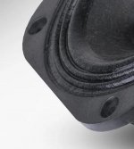
As I am somewhat allergic to roll surrounds, I'm looking for full range drivers with multiple wave accordion surrounds.
These offer at least 2 advantages:
- There's no surround sticking out, which makes mounting easier.
- Accordion surrounds usually go hand in hand with higher efficiency/sensitivity at the price of lower excursion (and higher Fs), which isn't troublesome in this case.
Series connection of 2 parallel-connected pairs of hornloaded drivers, each close to 90dB (8 Ohm) with an AES rating of around 30 W should suffice to keep up with a 15" covering 30-250Hz, or an octave higher.
Attachments
Last edited:
Hi all,
New measurement gear has arrived and I now have reliable measurements, with frequency response and impulse response looking as expected.
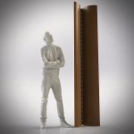
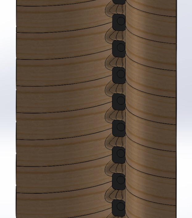
Meanwhile, Joseph has offered me a quote for a horn design for the array (see pictures which are a quick draft of the design). He also suggested the use of phase plugs to eliminate the cancellation effects in high frequencies. I do like the design and think it will fit perfectly size-wise on the sides of the book shelf. As of now I lean towards letting Joseph design the horns and use his CAD drawings to make a prototype for testing. What I’m not sure of is how wide/narrow dispersion that would be optimal with regard to my room. This controls the direct/reflected ratio in the listening position and amount of early reflections.
Comments and suggestions are welcome! 🙂


New measurement gear has arrived and I now have reliable measurements, with frequency response and impulse response looking as expected.
Meanwhile, Joseph has offered me a quote for a horn design for the array (see pictures which are a quick draft of the design). He also suggested the use of phase plugs to eliminate the cancellation effects in high frequencies. I do like the design and think it will fit perfectly size-wise on the sides of the book shelf. As of now I lean towards letting Joseph design the horns and use his CAD drawings to make a prototype for testing. What I’m not sure of is how wide/narrow dispersion that would be optimal with regard to my room. This controls the direct/reflected ratio in the listening position and amount of early reflections.
Comments and suggestions are welcome! 🙂
. He also suggested the use of phase plugs to eliminate the cancellation effects in high frequencies.
What I’m not sure of is how wide/narrow dispersion that would be optimal with regard to my room. This controls the direct/reflected ratio in the listening position and amount of early reflections.
This makes sense and it's is in line with my own thoughts concerning some sort of throat adapter > simply put, drivers + horns work better with an optimized connection.
Phase plugs are not only useful to eliminate cancellation effects, the overall frequency response might improve as well.
Perhaps Joseph could post some measurement data of his array, preferably including phase plugs 😉
Personally, I would be interested in measurements of a 'segment' of the array with 4 drivers.
In your room a(ny) horn loaded array is likely to perform better than a regular array, but I guess a coverage angle between 60 and (max.) 90° is more appropriate than a wider angle.
You might also consider asymmetrical horns.
Last edited:
This makes sense and it's is in line with my own thoughts concerning some sort of throat adapter > simply put, drivers + horns work better with an optimized connection.
Phase plugs are not only useful to eliminate cancellation effects, the overall frequency response might improve as well.
Perhaps Joseph could post some measurement data of his array, preferably including phase plugs 😉
Personally, I would be interested in measurements of a 'segment' of the array with 4 drivers.
In your room a(ny) horn loaded array is likely to perform better than a regular array, but I guess a coverage angle between 60 and (max.) 90° is more appropriate than a wider angle.
You might also consider asymmetrical horns.
Here's a comparison between the horn vs non-horn. The left column of measurements is the non-horn single driver... right is the E-250 horn with four SS 10F drivers. There is only one phase plug in between the two middle drivers. There is 0.10% distortion through the midrange with the horn... is this good performance compared to non-horn multiple driver line array? Please share if you've measured your line array. My mic distance was one meter.
Attachments
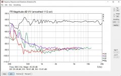
I have attached two graphs of my array, the first is a more recent indoor one with processing, the second is a raw outdoor one with no EQ. More of an orange to apples comparison given it is not on the same scale at the same spl etc....


The display ARTA gives is quite good for comparison of this sort of thing I'll try and check to see if ARTA can work with an REW measurement for a clearer comparison.
One thing I don't quite understand is the conversion of dB to percent that ARTA is using, according to the sengelpiel calculator, 0.1% is -60dB from the fundamental. I don't see your measurements having that much difference between fundamental and distortion components looks more like 50 to me from the image.
I would say that your result is very good 🙂 In my graph you can see the bottom brown trace which is the noise floor of the room as recorded by REW at the time of measurement. As you can see the distortion is below that for the majority of the time. Given that I don't see going lower as likely to have any audible benefit, especially given that harmonic distortion in speakers seems to be another thing most of the experts agree doesn't matter unless it is outrageous, which mine clearly is not.
I tend to use it more as a check of my room and equipment to make sure that nothing is faulty or broken than something I am actively looking to lower beyond what it already is. The exception to that would be in the bass where a subwoofer would make quite a difference as the distortion rises significantly due to the boost.
Attachments


What SPL level was used for the single driver vs horn comparisons? All distortion products look bundled together in both of them. I would expect measuring at higher SPL levels should have an effect and make distortion products look more like in fluid's graph.
Not saying I'm not impressed with the results though. I measure at 2.7 m and about 80 dB levels (calibrated with an SPL meter) and get about ~0.5 to 0.6 from 200 Hz and up.
Not saying I'm not impressed with the results though. I measure at 2.7 m and about 80 dB levels (calibrated with an SPL meter) and get about ~0.5 to 0.6 from 200 Hz and up.
In response to the above distortion sweeps I've changed my measurement settings to display dB instead of %THD. I've selected a volume level that produced the least distortion for the non-horn speaker and then level matched the horn speaker's to the non-horn. This ensured I wasn't stressing the non-horn speaker which would invalidate the comparison. So the horn is -60dB from the fundamental (0.10%) while the non-horn is -48dB (0.80%), looking at 1kHz region.
Attachments
That is what I figured, but that makes this comparison moot.
As what's being measured with the arrays, at least in my case is at the listening spot at or around 80 dB. (confirmed by an SPL meter)
From 20 to 20 Khz... with 2x 12"subs added I have it below 1% in the entire region. About 0.5 to 0.6 from 200 Hz and up,
the subs come in to help out at ~160 Hz. Still need to fine tune.
What is obvious though is that dip due to the horn geometry.
Adding a horn can improve that, but I don't like that dip though. What can we do to improve that performance...
Last edited:
I don't think anyone needs to be convinced that using a horn increases efficiency and thus lowers distortion where the horn has gain.
How can we harness horns for a line array?
An intriguing picture of a line array horn was posted. What can you tell us about that horn's measured or expected or simulated performance?
How can we harness horns for a line array?
An intriguing picture of a line array horn was posted. What can you tell us about that horn's measured or expected or simulated performance?
- Home
- Loudspeakers
- Full Range
- Another corner line array, 28 TC9FD18