Looking back in this thread and can’t really give up the idea of a horn like the one Joseph proposed. Maybe like this and putting subs below and on top:
What do you think?
Only 16 Tc9:s left but I figure I would still be able to control the vertical directivity. The outer ones were cut pretty low in my earlier Vituix sims anyway.
The horizontal directivity however...I don’t have the knowledge/experience with horns to really understand their behavior or do reliable simulations. A bit worried what happens where the horn and wall meet.
Danley makes product like that which uses paralines instead of full range drivers. Looking at it might help. I would second what Ronald said about needing a termination at the mouth. I would not worry so much about the wall. Within the pattern control frequency range of the horn, the radiation won't hit the wall. Below it you will have the same boundary interference issue you would have with a direct radiator, closing the circle back to absorption.
You need to worry about the horn throat even more so than the mouth - look at what Joseph did. If the throat isn't done well, the high end will suffer. As to both mouth and throat, the profiles that work for mabat in the ATH thread rotated around an axis should work just as well for you extruded into a line, except for the shape needed between drivers, if any.
But I would not do a horn for drivers as large as a TC9. The throat anomalies will be lower in frequency and thus more problematic than those that exist in a 1" throat. The TC9's response is not so wide up top that you need a horn to shape it and beaming will prevent the horn pattern from being filled.
I can more easily connect the vertical top end from Follgott to the driver's top end measurements than the simulations as shown by Crumboo.
Hm, yes it seemed too good to be true 😱
I checked the settings in Options and the Angle step was set to 15 deg, producing this polar:
Reducing the Angle step to 10 deg:
And then to 5 deg:
Maximum SPL is thus 5 degrees above listening position (about 2.5 dB more than in the seating/design position):
So, the SPL is at maximum in between the seated and standing position. Maybe the results now are more as expected...
We should keep in mind that this is interpolated data (measurement were only at 0, 15, 30, 45 and 60 degrees). When the drivers arrive I will do a set with more closely angled measurements.
Attachments
Pfew, that really does make a difference. Hope to see some real life measurements soon!
It does show that even with ribbon drivers, it isn't easy to get consistent output up high over a wider vertical angle.
It does show that even with ribbon drivers, it isn't easy to get consistent output up high over a wider vertical angle.
One thing that I found and I think could have potential to widen the vertical response up high is using such "foam deflection pads" like for the RAAL 140-15D. As shown in the link there could be some substantial improvements! When I get the driver I will definitely experiment with this! Like a shading of the ribbon/AMT. 🙂
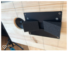
The Beyma 200/B:s have arrived and I finally got some time for directivity measurements:
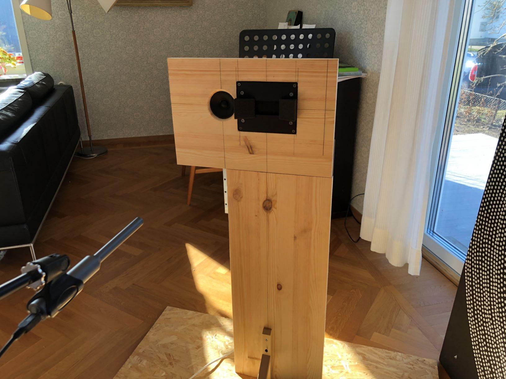
All measurement were made with the mic 60 cm from the baffle and a 4 cycle FDW was used.
Measuring vertical and horizontal response in 10 deg increments from 0 to 90 degrees.
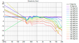
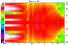
Normalized horizontal response for 200/B:
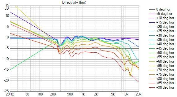
Giving this polar:

Much better I think! 🙂
The foam wedges results in a loss of sensitivity, but as the sensitivity of these drivers are so high this would not be of any concern I think.
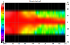
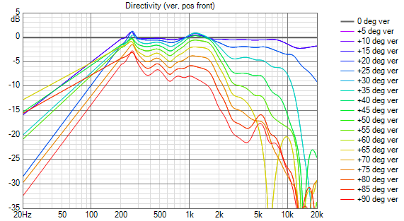
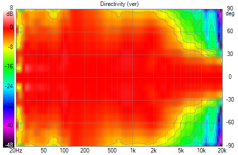
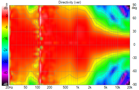
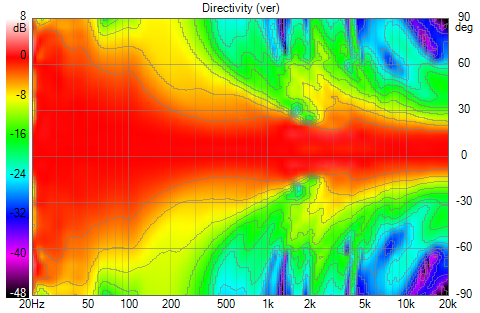
In the vertical direction:
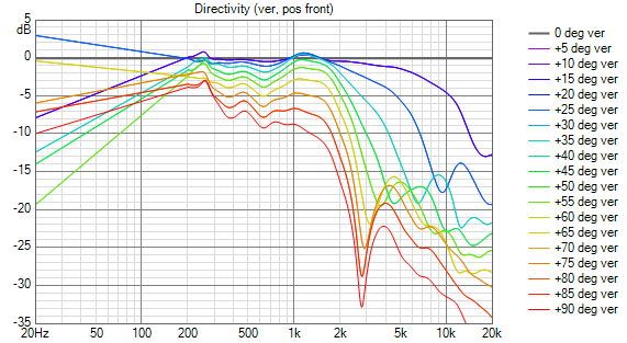
And this polar:
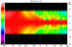
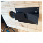
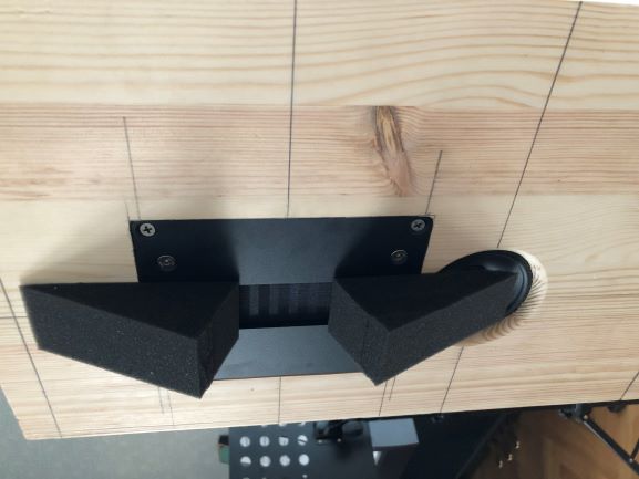
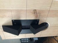
It gets super narrow in the top end... so I did some experiments using foam wedges to physically "shade" the driver. The most promising looks like this:
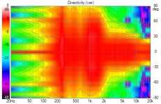
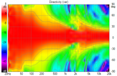
Now, the response gets as this:
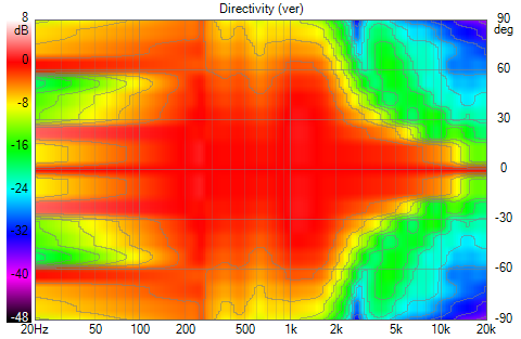
Giving this polar:
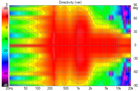
Pretty nice I think!
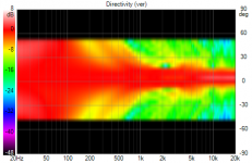
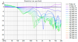
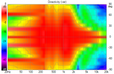
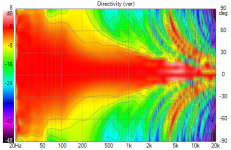
For reference, here are the results for the Vifa TC9F:
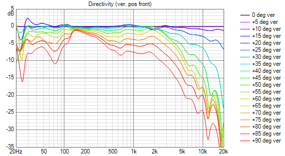
And polar:
All measurement were made with the mic 60 cm from the baffle and a 4 cycle FDW was used.
Measuring vertical and horizontal response in 10 deg increments from 0 to 90 degrees.
Normalized horizontal response for 200/B:
Giving this polar:
Much better I think! 🙂
The foam wedges results in a loss of sensitivity, but as the sensitivity of these drivers are so high this would not be of any concern I think.
In the vertical direction:
And this polar:
It gets super narrow in the top end... so I did some experiments using foam wedges to physically "shade" the driver. The most promising looks like this:
Now, the response gets as this:
Giving this polar:
Pretty nice I think!
For reference, here are the results for the Vifa TC9F:
And polar:
Attachments
-
 VituixCAD Directivity (ver, pos front)_vifa.png47.4 KB · Views: 441
 -
 VituixCAD Directivity (ver, pos front)_7_nointerp.png50.6 KB · Views: 431
 -
 VituixCAD Directivity (ver, pos front)_0_nointerp.png47.7 KB · Views: 422
 -
 VituixCAD Directivity (ver)_nointerp.png124.3 KB · Views: 428
 -
 VituixCAD Directivity (ver)_7_nointerp.png134.9 KB · Views: 440
 -
 VituixCAD Directivity (hor, pos front)_7_nointerp.png41 KB · Views: 432
 -
 VituixCAD Directivity (hor)_7_nointerp.png107.5 KB · Views: 434
 -
 kilar.png64.9 KB · Views: 425
 -
 VituixCAD Directivity_vifa.png106 KB · Views: 442
 -
 IMG_3869.jpg209.8 KB · Views: 433
Certainly interesting. So nude it tends to have that needle point vertical behavior at high frequencies. The wedges sure help!
It will be interesting to find out how smooth you can combine the array + tweeter.
It will be interesting to find out how smooth you can combine the array + tweeter.
Interesting waveguide from 18sound to go with their new AMT
Eighteen Sound - Professional loudspeakers
Eighteen Sound - Professional loudspeakers
Interesting waveguide from 18sound to go with their new AMT
Eighteen Sound - Professional loudspeakers
Yes, interesting. But the second image shows a very narrow needle like response, or do I miss something here?
I made lots of more measurements with different variations of that foam wedge, and this looks even better:
Which gives this polar:
My best effort yet for the array (without the centre tweeter) have this polar:

It looks to that the best place to mate these two is around 3500 Hz. With 2nd order linear phase filters at 3500 Hz I get this polar:
Response like this:

While I think it is a good start, I'm not happy yet - the directivity dip in the 3-5 kHz range should be evened out. There are so many parameters to tweak in Vituix, both passive components for the array shading, filter slopes and things like phase eq:s etc...
Which gives this polar:
My best effort yet for the array (without the centre tweeter) have this polar:
It looks to that the best place to mate these two is around 3500 Hz. With 2nd order linear phase filters at 3500 Hz I get this polar:
Response like this:
While I think it is a good start, I'm not happy yet - the directivity dip in the 3-5 kHz range should be evened out. There are so many parameters to tweak in Vituix, both passive components for the array shading, filter slopes and things like phase eq:s etc...
Attachments

The vertical is very narrow because of the length of the driver. A combination of a waveguide like that to control the horizontal together with the foam wedges could help tailor the directivity in both directions and maybe avoid the lumpy polar you get from a mismatch between the line and the AMT.Yes, interesting. But the second image shows a very narrow needle like response, or do I miss something here?
smoothing the directivity between array and waveguide has been the conundrum in all the like vituix simulations I've done. The best handle I've found is varying the XO filter slopes which indirectly controls the overlap and the overlap itself (different corner freq between high and low pass) between the narrowing array and the widening waveguide. Finally the array characteristics matter. IIRC, a line array narrows too quickly; an expanding array where the CTC doubles from one MTM pair of element to the next does better. My best results have been expanding array where the 2nd element is an small array that covers most of the distance from where it starts to floor or ceiling. One of the benefits of that is the same/similar low frequency pattern control as from a line array.
I made lots of more measurements with different variations of that foam wedge, and this looks even better:
Which gives this polar:
My best effort yet for the array (without the centre tweeter) have this polar:
It looks to that the best place to mate these two is around 3500 Hz. With 2nd order linear phase filters at 3500 Hz I get this polar:
Response like this:
While I think it is a good start, I'm not happy yet - the directivity dip in the 3-5 kHz range should be evened out. There are so many parameters to tweak in Vituix, both passive components for the array shading, filter slopes and things like phase eq:s etc...
I believe the proof how smooth it really is, is clear only when you do check out the heights of interest. So you'd need to move the mic position relative to the speaker and check it's output. As the mic is fixed at zero, you need to move all drivers relatively to the mic (using the driver Y offset) and alter the floor and ceiling distances to correspond.
So if you use a distance of y=-100, subtract 100 from both ceiling and floor numbers, you have moved the mic 100 mm upwards, etc.
You can save the traces you get when moving the mic in the left middle graph (Power & DI) by right-clicking the in-room prediction and choosing "Save selected as overlay". It may deviate somewhat from the vertical angle graph.
The vertical is very narrow because of the length of the driver. A combination of a waveguide like that to control the horizontal together with the foam wedges could help tailor the directivity in both directions and maybe avoid the lumpy polar you get from a mismatch between the line and the AMT.
Yes, I understand now. I haven't started to look much on taming the horizontal directivity yet. For the measurements so far it is pretty wide and uniform, but I have hopes to get it better controlled to reduce wall reflections. For now I'll keep digging into the vertical dispersion and solve that first.
smoothing the directivity between array and waveguide has been the conundrum in all the like vituix simulations I've done. The best handle I've found is varying the XO filter slopes which indirectly controls the overlap and the overlap itself (different corner freq between high and low pass) between the narrowing array and the widening waveguide. Finally the array characteristics matter. IIRC, a line array narrows too quickly; an expanding array where the CTC doubles from one MTM pair of element to the next does better. My best results have been expanding array where the 2nd element is an small array that covers most of the distance from where it starts to floor or ceiling. One of the benefits of that is the same/similar low frequency pattern control as from a line array.
As I wrote - there are so many parameters to tweak! I haven't touch the driver spacing yet, but I will look into it - thanks for the tip! How do you mean by
?the 2nd element is an small array that covers most of the distance from where it starts to floor or ceiling
Something I really wish for in Vituix is the possibility to set a target curve for the directivity index and optimise on that. The on-axis response could then always be restored with a FIR/mirror...
I believe the proof how smooth it really is, is clear only when you do check out the heights of interest. So you'd need to move the mic position relative to the speaker and check it's output. As the mic is fixed at zero, you need to move all drivers relatively to the mic (using the driver Y offset) and alter the floor and ceiling distances to correspond.
So if you use a distance of y=-100, subtract 100 from both ceiling and floor numbers, you have moved the mic 100 mm upwards, etc.
You can save the traces you get when moving the mic in the left middle graph (Power & DI) by right-clicking the in-room prediction and choosing "Save selected as overlay". It may deviate somewhat from the vertical angle graph.
Something like this?
I moved up in 100 mm increments until +800 mm, which would be my standing listening position. Sorry for not naming the traces, it's hard to follow from the label. It's not super bad I think, but surely it could be better! 🙂
EDIT: Ah, I now see that it was the in-room prediction curve I was supposed to save...
Attachments
Last edited:
lol, yes... floor and ceiling add to this game for the predicted in-room results.
But it doesn't seem to give bad results! The tweeter holds up nicely even if it is shelved down a bit.
But it doesn't seem to give bad results! The tweeter holds up nicely even if it is shelved down a bit.
Here we go again! Lots of simulations and trying to get a good combination of smoothness in directivity/power response, coverage of the vertical listening (reasonable good response at standing position) and trying to minimise floor and ceiling reflections. This is where I am at the moment:
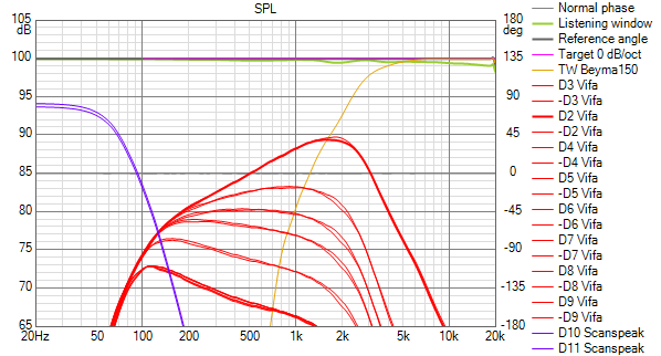
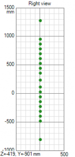
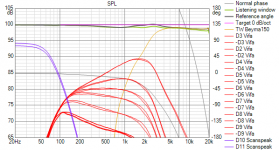
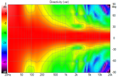
Polar plot. Note that the tweeter is positioned in the middle between floor and ceiling, which is 242 mm above seated listening position:

SPL curves of the drivers:
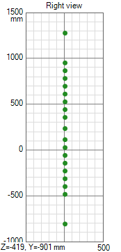
I have now replaced the four outermost Vifas in the array for 2 12" subwoofers (thinking of the same drivers as Wesayso used for his subs). 16 Vifas left, 8 above and 8 below the tweeter:
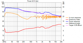
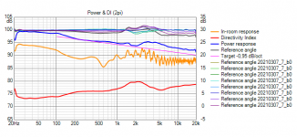
Power and DI plot:
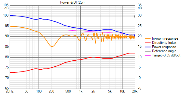
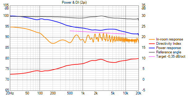
Now, moving up to standing position we get the following:
I think I'm getting close to something useful here.
The schematics looks like this:
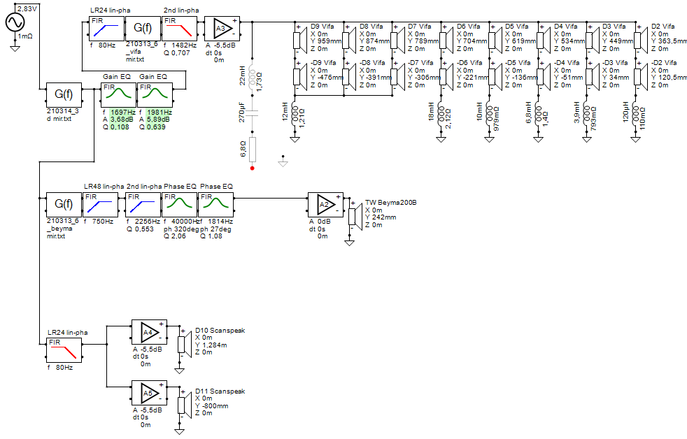
A key here was to make a gradual phase turn on the tweeter up high, and also some phase eq at the "cross over". I know that the wiring of the Vifas results in a pretty low impedance (about 2 Ohms), so I will do something to fix this also. But I start to like what I see here! 🙂 What do you guys think?
Polar plot. Note that the tweeter is positioned in the middle between floor and ceiling, which is 242 mm above seated listening position:
SPL curves of the drivers:
I have now replaced the four outermost Vifas in the array for 2 12" subwoofers (thinking of the same drivers as Wesayso used for his subs). 16 Vifas left, 8 above and 8 below the tweeter:
Power and DI plot:
Now, moving up to standing position we get the following:
I think I'm getting close to something useful here.
The schematics looks like this:
A key here was to make a gradual phase turn on the tweeter up high, and also some phase eq at the "cross over". I know that the wiring of the Vifas results in a pretty low impedance (about 2 Ohms), so I will do something to fix this also. But I start to like what I see here! 🙂 What do you guys think?
Attachments
-
 driver_layout.PNG5.7 KB · Views: 345
 -
 20210314_3_standing SPL.png46.1 KB · Views: 95
 -
 20210314_3_standing Power+DI (2pi).png28.1 KB · Views: 339
 -
 20210314_3_seated SPL.png41.6 KB · Views: 348
 -
 20210314_3_seated Power+DI (2pi).png27.4 KB · Views: 351
 -
 20210314_3_seated Directivity (ver).png141.5 KB · Views: 355
 -
 20210314_3_seated2 XO-schema-1.png40.9 KB · Views: 356
If you can get it to work like that, it would be awesome! The trick you used on the Vifa line to tweeter might work on the sub to Vifa line as well for an even more smooth directivity.
Smoothing out the dip at 200 Hz even further, but this does seem like a winner.
I think I should add my subs in my sims as well, just to play with them. What kind of directivity files did you use for the sub? Did you generate it from a 12" driver in Vituix?
I remember seeing a 16 ohm Vifa TC or TG series once, but they don't show up in stores. The 2 ohm is a bit too low for safety.
Last edited:
As I wrote - there are so many parameters to tweak! I haven't touch the driver spacing yet, but I will look into it - thanks for the tip! How do you mean by
?
Something I really wish for in Vituix is the possibility to set a target curve for the directivity index and optimise on that. The on-axis response could then always be restored with a FIR/mirror...
By the 2nd element, I meant the 2nd out from the tweeter. You would have tweeter, close in MTM driver pair, line arrays to floor & ceiling. And those line arrays would be frequency shaded - which is where you ended up.
Good work!
@crumboo, just a friendly word of advise...
With results this good, don't forget about the (close by) side walls. The above would work wonders on floor and ceiling to create more than acceptable results for seated and standing in-room results. However to get the max out of it, the side walls, that for a large part will be parallel to the arrays, will have a huge influence too. So do factor that in somehow. At least to avoid (very) early reflections of close by boundaries.
That will be something to factor in, as it will be roughly equal distance to all of those array drivers, which makes it less forgiving.
- Home
- Loudspeakers
- Full Range
- Another corner line array, 28 TC9FD18