right!
and if I add 15" woofers to the top and bottom of the previous sim, I get some control over the vertical circa 200 Hz but there still is excessive influence in that lower midrange so more work to be done

and something like that is bigger than I want to build
15" woofers at +/-750 mm from wg 1m above floor
and if I add 15" woofers to the top and bottom of the previous sim, I get some control over the vertical circa 200 Hz but there still is excessive influence in that lower midrange so more work to be done
and something like that is bigger than I want to build
15" woofers at +/-750 mm from wg 1m above floor
Attachments
That is starting to look smooth though. It would be interesting to find out if one can steer that beam to be of a certain size. Indeed these would be big! But you may get similar results with a row of less wide drivers, but one needs that tall/wide waveguide anyway?
A 15" woofer up high is just too much.
I'm going to try that larger waveguide with lower XO next. I think that will help. But there is a limit beyond which you need to synergize or use that monster Celestion AXI2050
Then use enough small midwoofers to get the bass without the concentrated weight. I will try two columns with perhaps half wavelength spacing at 500 Hz XO
Fluids larger waveguide is 472mm diameter so it will fit on my .5m wide baffle. From his thread, I'll assume it will be Synergized. I can then overlap it with lines of midbasses above and below. If the speaker is in a corner it will get bass H pattern control from that.
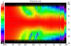
Where does this wg lose pattern control? @fluid - your directivity files only go down to 600 Hz! What happens below?
Where does this wg lose pattern control? @fluid - your directivity files only go down to 600 Hz! What happens below?
From the graphs, the wg gradually widens below 1 Khz, with complete loss around 250 Hz. It might only need rows of midwoofers top and bottom
I'm not so sure that I do understand quite what you are getting at here.I think you know what I'm getting at 🙂
Anechoically the waveguide is about as good as you can get between 800Hz and 10KHz which I think is the most important region.Figure out what you'd want ideally, everything above 7 KHz to be perfect or everything between ~100 up to 7 KHz to be perfect.
My main desire for trying a waveguide is to see whether that translates into in room performance, because we can see from the room simulations that the multiple sources of the array look better in that regard, but the question remains do they sound better. In the same way that combing of the array top end looks bad it does not sound bad.
Can the ear and brain combination work to separate the anechoic response from the room response, or is the measured response closer to the perceived response. I don't know yet.
I agree in principal but I suspect that the marriage will be tricky.But what I'm getting at is that we shouldn't settle for anything less than what it already does well. Which means that a transition of a horn to the lower frequencies should be at least as seamless as a single idealized source.
I think the current explorations are interesting and whilst not ideal are much better than previous tries particularly when not symmetrical about the horn.All this is leading towards an expanding array with Synergy at center and the question for me is how big that center Synergy waveguide needs to be to avoid compromises or excessive room influence in the low midrange. Some form of that question has been around for some time. At least now the solutions we are coming up with are starting to look fairly good.
It is tricky and I agree that there are options to consider to improve the full range array further. I shading is one part, the acoustic combination of the drivers and how the pattern could be shaped through the enclosure of front guides has yet to be explored. I am interested in exploring those options but I am somewhat bogged down to do much with it right now. If you want to put your CAD skills to use it could well change the order of priorities 🙂A fusion of some sort seems to have ideal properties....
That's the puzzle I'm seeing here... 🙂
Meanwhile I'll be looking at ways to improve the full range array, as I do believe we could soften the side bands with some help in directivity pattern control
Which means if we could shape this output at will, to come closer to something that works well in such an array, another step up in performance is waiting there. If there aren't some real compromises that can undermine this line of thought.[/I]
It will give out slowly like all the others but I will have to run the simulation again and use a lower frequency to get that information. I haven't worried too much as without a lumped element model of the compression driver the results are unlikely to be realisable in practice even though that is the pure directivity of the waveguide.Where does this wg lose pattern control? @fluid - your directivity files only go down to 600 Hz! What happens below?
I'm not so sure that I do understand quite what you are getting at here.
Never mind, I can't make it more clear than I've done. I would say we want a single controlled source, but we'll have to make it ourselves as it doesn't exist. A full range pretends to be like that, but isn't ideal. A horn can do part of it, but also falls short. Make the horn larger and the top end begins to suffer too...
(use a bigger full range drivers, better bottom end, worse top end. Use smaller full range driver, better top end, worse bottom end. A 3" to 4" full range could be considered close to being able to somewhat honor its name. nehhh 😛 at least not a single one, actually, there isn't one that really can)
[this probably doesn't help at all, all I was getting at is that if one substitutes a full range driver by a horn, the rest of it below the horn should still be as good/smooth as that full range driver (or array) can accomplish. The sims are moving in the right direction for that to happen. There was a lot more going trough my head, but I can't find a good way to express that, put it into words. In short: I'm still fascinated by creating the better solution than a single source full range. An array like I've build (or the fractal solution etc.) is one way, a horn/synergy type is another. I can't think of many more solutions that come close]
Anechoically the waveguide is about as good as you can get between 800Hz and 10KHz which I think is the most important region.
My main desire for trying a waveguide is to see whether that translates into in room performance, because we can see from the room simulations that the multiple sources of the array look better in that regard, but the question remains do they sound better. In the same way that combing of the array top end looks bad it does not sound bad.
I know and understand your reasons to build the horn speaker. Well understood. 🙂
On the subject of combing:
In every confined space we'll hear some form of combing. We are used to that, but getting rid of it would most probably be the better choice at any time. Just like getting rid of diffraction as much as we can, which leads to less obvious patterns. Ask anyone that creates a simple rectangular shaped speaker what he thinks about diffraction. Most common answer? I've never heard diffraction to be a problem... I'll just shift the tweeter to one side.
Can the ear and brain combination work to separate the anechoic response from the room response, or is the measured response closer to the perceived response. I don't know yet.
Well, I do or can believe we can. Using the logic of Toole, that we can actually separate the direct sound from the reflections. Similar as recognizing the voice of someone in different acoustical environments/rooms, we will be able to recognize the 'sound print' of the speaker within the room. This doesn't mean the room will not color the sound, hence the scrutiny of keeping off axis patterns in check, so the total tonal balance we perceive isn't shifted too much.
I agree in principal but I suspect that the marriage will be tricky.
I think the current explorations are interesting and whilst not ideal are much better than previous tries particularly when not symmetrical about the horn.
That's where the comparison to a (pure) full range source comes up again. As said, ideally you'd want the speaker to act as close as possible to one source, even if it consists of multiple drivers plus a horn to get there. Not an easy task for sure!
It is tricky and I agree that there are options to consider to improve the full range array further. I shading is one part, the acoustic combination of the drivers and how the pattern could be shaped through the enclosure of front guides has yet to be explored. I am interested in exploring those options but I am somewhat bogged down to do much with it right now. If you want to put your CAD skills to use it could well change the order of priorities 🙂
If I have an idea of what's needed, I can probably supply the needed models to start digging 😉. I'm more used to creating solid models, but if I know what's needed I should be able to supply it. I would probably mean I need to simplify my existing enclosure model, deliver a cone shape (with or without surround?) and get rid of all inside details that don't matter for this task.
Next we need to find out what resolution the meshes should be at.
Last edited:
This doesn't mean the room will not color the sound, hence the scrutiny of keeping off axis patterns in check, so the total tonal balance we perceive isn't shifted too much.
This is something that the horn can do very well too, the off axis control should make any reflections be as spectrally similar as possible. Whether that matters or is an improvement on what I have now remains to be seen.
There is no issue with the model being solid, gmesh will just mesh the surfaces but reducing the amount of unnecessary surfaces helps to keep the mesh size down for loading. The full cone shape including surround could be useful and if meshed in one go it can help make the vertices line up.If I have an idea of what's needed, I can probably supply the needed models to start digging 😉. I'm more used to creating solid models, but if I know what's needed I should be able to supply it. I would probably mean I need to simplify my existing enclosure model, deliver a cone shape (with or without surround?) and get rid of all inside details that don't matter for this task.
Next we need to find out what resolution the meshes should be at.
If a driver is meshed separately it often has to be used as a template to cut the baffle to make sure the vertices line up correctly.
When exporting to step I just hide all the stuff I don't want or need in the export.
Probably the best place to start would be something like your small test speaker that you made, trying different mounting or waveguide shapes on that to see which direction to go before moving onto smaller lines.
The diaphragm itself can be simulated in ABEC with a few dimensions and no separate mesh needed.
Using your test box as a template might be useful as it could be compared against the real thing to see if the model has validity.
I've got some polars despite the shortcoming of the directivity files. It appears that Vituix does a fair job of extrapolating downwards in frequency.
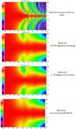
For a row of midwoofers above and below the array, these charts show results for XOs of 600, 500, 400 Hz from top down. The right hand graphs are both sets of drivers; the left hand charts are the un-normalized vertical polars of the mids alone.
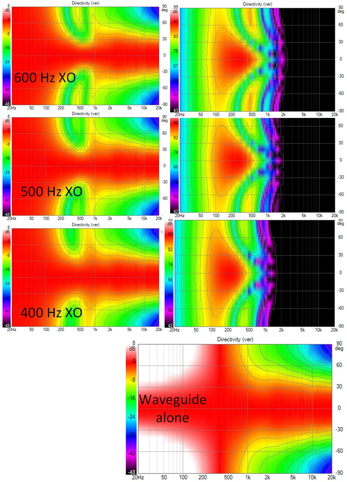
The CTC is too high for greater than 400 Hz XO, the directivity of the WG is too low for even a 600 Hz XO.
Things look better when the midwoofers are on a circular arc. The effective CTC is smaller since all drivers are same distance from axis instead of at increasing distance for the ones further from the axis
For a row of midwoofers above and below the array, these charts show results for XOs of 600, 500, 400 Hz from top down. The right hand graphs are both sets of drivers; the left hand charts are the un-normalized vertical polars of the mids alone.
The CTC is too high for greater than 400 Hz XO, the directivity of the WG is too low for even a 600 Hz XO.
Things look better when the midwoofers are on a circular arc. The effective CTC is smaller since all drivers are same distance from axis instead of at increasing distance for the ones further from the axis
Attachments
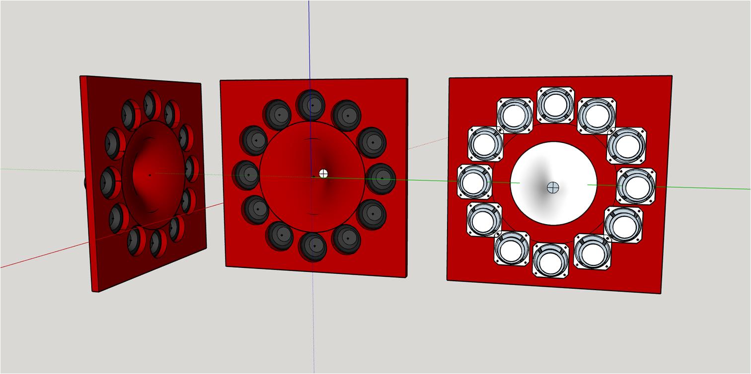
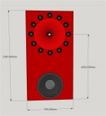
Here are the polars for the mids on an arc of 336mm radius. There are 12 drivers at the hour marks of a clock with the drivers at 3 and 9 oclock muted. The baffle has to grow to 600mm wide for this but the 4 drivers over the +/-250 mm X mark do extend the H pattern control
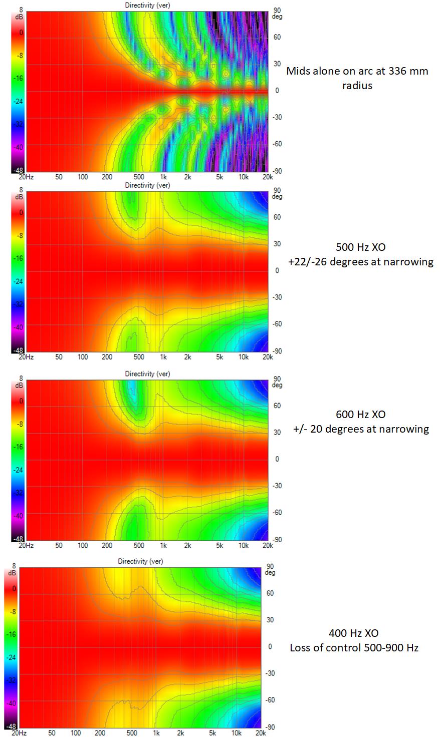
These sims where done absent floor and ceiling reflections to focus on XO and CTC issues. With XO in the 500 Hz to 600 Hz range, the wg doesn't need to be synergized. Alternatively, one could design for 1" exit driver and synergize using the 4" Celestion sealed back mids.
These sims where done absent floor and ceiling reflections to focus on XO and CTC issues. With XO in the 500 Hz to 600 Hz range, the wg doesn't need to be synergized. Alternatively, one could design for 1" exit driver and synergize using the 4" Celestion sealed back mids.
Attachments
There is no issue with the model being solid, gmesh will just mesh the surfaces but reducing the amount of unnecessary surfaces helps to keep the mesh size down for loading. The full cone shape including surround could be useful and if meshed in one go it can help make the vertices line up.
If a driver is meshed separately it often has to be used as a template to cut the baffle to make sure the vertices line up correctly.
When exporting to step I just hide all the stuff I don't want or need in the export.
Probably the best place to start would be something like your small test speaker that you made, trying different mounting or waveguide shapes on that to see which direction to go before moving onto smaller lines.
The diaphragm itself can be simulated in ABEC with a few dimensions and no separate mesh needed.
Using your test box as a template might be useful as it could be compared against the real thing to see if the model has validity.
Lets continue this on my thread, not to mess up Jack's research here 🙂.
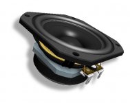
I thought the TC9's on this picture looked a little funny (more like a scaled up version of a SB65WBAC25). 🙂
My model of it is still up: http://www.rsr-concepts.com/diyma/Vifa-Branded.zip

My model of it is still up: http://www.rsr-concepts.com/diyma/Vifa-Branded.zip
Attachments
Last edited:
The Horn needs rotating 90 degrees clockwise too, the STL output from Ath needs rotating if it's not Axisymmetric. Not that is matters for a quick visualization 🙂I thought the TC9's on this picture looked a little funny (more like a scaled up version of a SB65WBAC25). 🙂
Switching to TC9 mids improves the picture. The baffle was too wide for 5FE120 clock face. CTC improves marginally with TC9s. But I'm back to using that same fake model.

The polars are great but there is a floor bounce null at 300 Hz
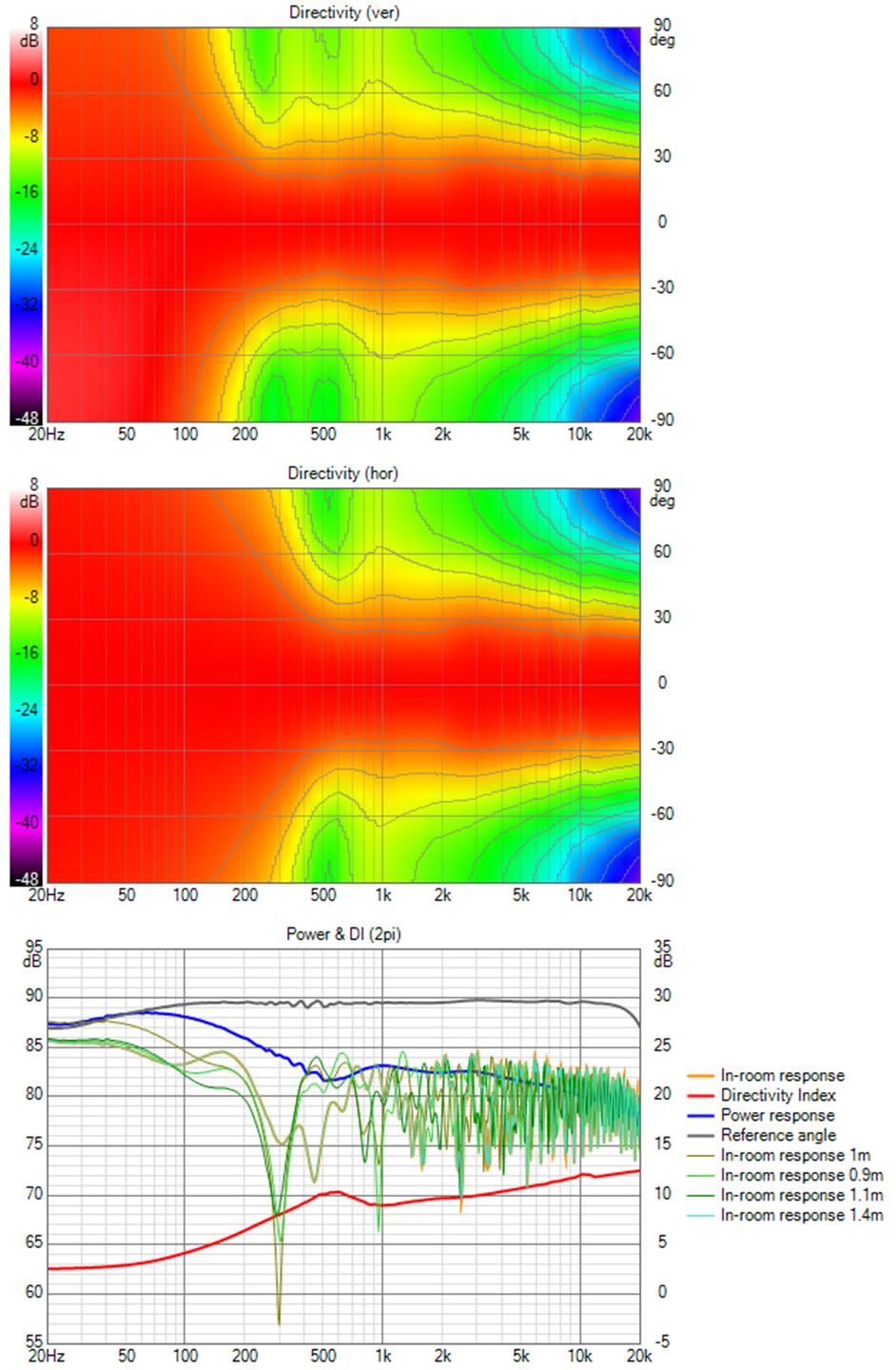
That null is inherent in the wg and tc9 center to floor distance and is there with either or both of those two drivers playing. I can fill it somewhat from the woofer but that, as I showed not that long ago, would be a precarious balance.
The polars are great but there is a floor bounce null at 300 Hz
That null is inherent in the wg and tc9 center to floor distance and is there with either or both of those two drivers playing. I can fill it somewhat from the woofer but that, as I showed not that long ago, would be a precarious balance.
Attachments
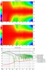
Could you try the Allison arrangement of crossing the TC9's above the notch frequency so only the woofer is contributing and being on the floor would not give a bounce in the same way?
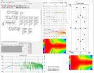
Lacking a better idea, I tried replacing the TD15 with pairs of 8" woofers just above and below the circle of TC9s

This gave vertical directivity at 300 Hz albeit and the floor bounce null is moderated although its hard to see how much without smooting the room responses

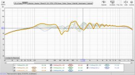
For the above graph I flattened the room response. Only floor and ceiling reflections are enabled. REW insisted on highlighting the 400 mm offset line. This is pretty good for seated listening at 3m; somewhat disappointing in the amount of reflections seen above 1 khz, I expected less given the apparent directivity...
This gave vertical directivity at 300 Hz albeit and the floor bounce null is moderated although its hard to see how much without smooting the room responses
For the above graph I flattened the room response. Only floor and ceiling reflections are enabled. REW insisted on highlighting the 400 mm offset line. This is pretty good for seated listening at 3m; somewhat disappointing in the amount of reflections seen above 1 khz, I expected less given the apparent directivity...
Attachments
- Home
- Loudspeakers
- Full Range
- Full range line array for wall or corner placement