I added a TD15 woofer at floor level and enabled reflections. The room response overlays in the middle graph are +/- 100 and 200 mm offsets from nominal mic ht of 1m, There XO is set at 800 Hz with very little narrowing of H pattern. The narrowing increases if XO is raised...
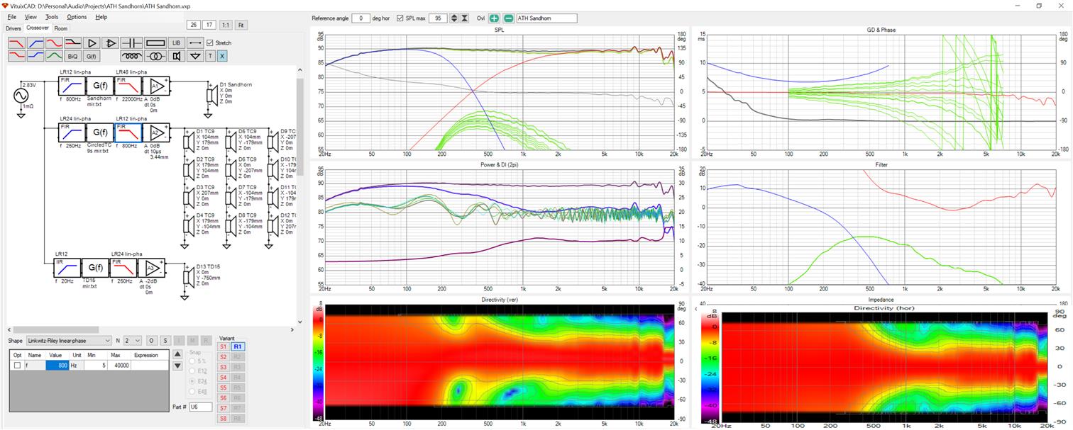
This horn is 60H so wall reflections are smaller than with seos18. The response variation with height is smaller also.
With this smaller wg and omitting the 3 and 9 PM TC9s, the cabinet will be narrower. Now for an ATH waveguided designed to terminate in a baffle...
This horn is 60H so wall reflections are smaller than with seos18. The response variation with height is smaller also.
With this smaller wg and omitting the 3 and 9 PM TC9s, the cabinet will be narrower. Now for an ATH waveguided designed to terminate in a baffle...
Attachments

Nice work, I've attached a pretty good squareish guide in Vituix format that you can play with. I have a round version too but haven't exported the data.
What about overlapping the woofer like you did in the simulations before, that seemed to work well.

Mark any chance you can wrap your images in
tags so we don't have to leave the page to see them full size?
What about overlapping the woofer like you did in the simulations before, that seemed to work well.
Mark any chance you can wrap your images in
Code:
[IMG] [/IMG]Attachments
Last edited:
@fluid
Your waveguide works quite well flanked by 5 TC9s each just above and below and with a 15" woofer at floor level. 5 TC9s exceed the width of the wg so the horizontal pattern controlled is extended. CTC doesn't allow XO to the TC9s high enough to keep the vertical pattern from widening a little bit above XO. A quick look tells me that some overlap between the tc9s and the CD cures that so I will work on that next
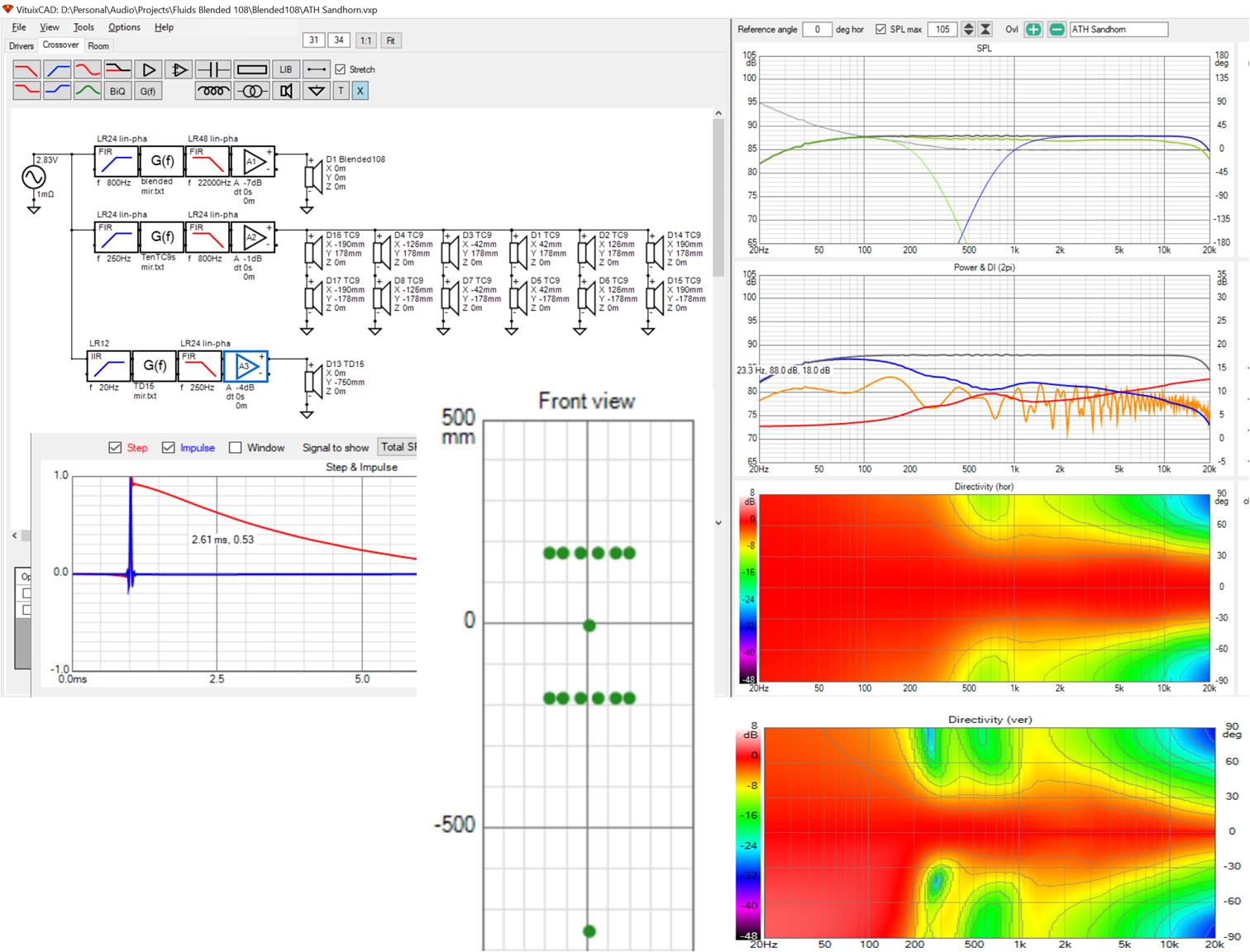
Your waveguide works quite well flanked by 5 TC9s each just above and below and with a 15" woofer at floor level. 5 TC9s exceed the width of the wg so the horizontal pattern controlled is extended. CTC doesn't allow XO to the TC9s high enough to keep the vertical pattern from widening a little bit above XO. A quick look tells me that some overlap between the tc9s and the CD cures that so I will work on that next
Attachments
Overlap narrows the vertical, perhaps too much. Just a little bit is all that is needed.
High pass on CD/wg is 800 Hz. With low pass on TC9s at 1000 Hz:
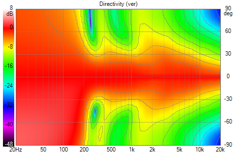
which might not be enough
with low pass on TC9s at 1300 Hz:
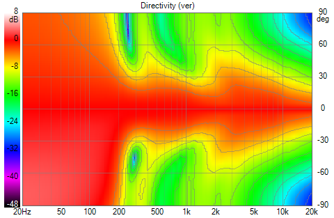
which is clearly too much
with low pass at 1100 Hz
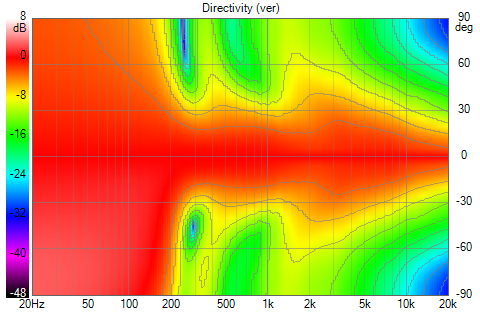
which is as far as I would go.
The overlap causes a 2 db or so hump in the FR in the overlap region. This can be flattened with a PEQ or by a room/global EQ stage, which is what I did for the sim.
High pass on CD/wg is 800 Hz. With low pass on TC9s at 1000 Hz:
which might not be enough
with low pass on TC9s at 1300 Hz:
which is clearly too much
with low pass at 1100 Hz
which is as far as I would go.
The overlap causes a 2 db or so hump in the FR in the overlap region. This can be flattened with a PEQ or by a room/global EQ stage, which is what I did for the sim.
Attachments


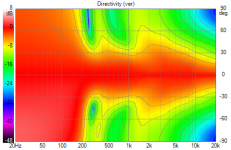
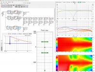
Its easier to judge the overlap with all the graphs side by side.
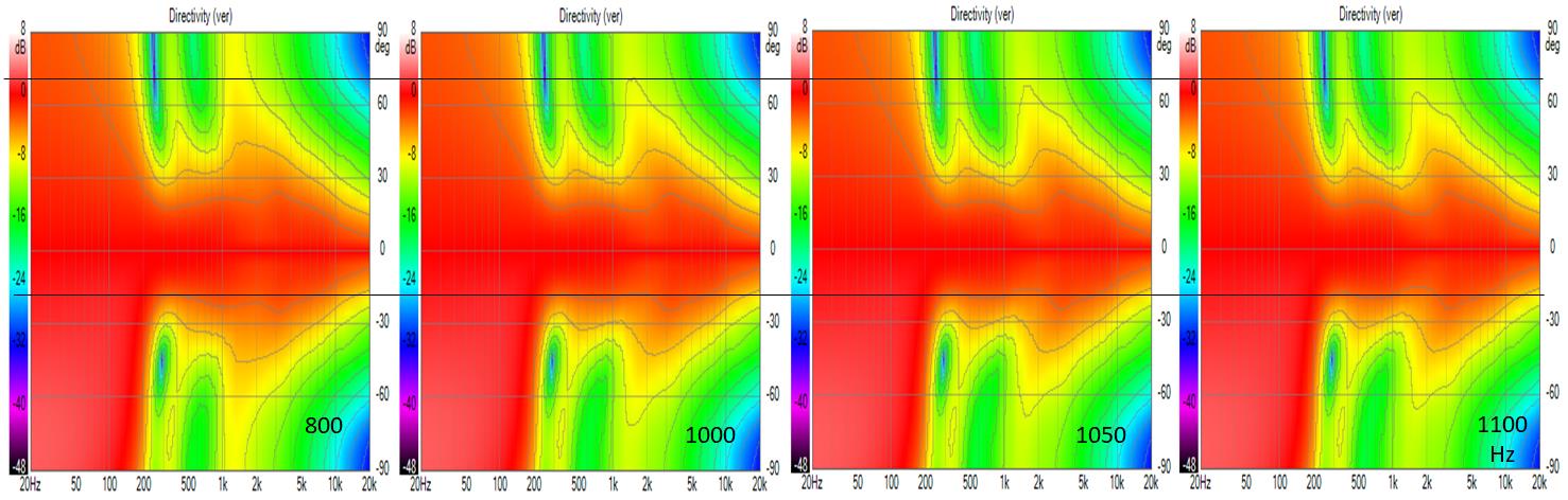
I added two reference lines to the composite.
The upper line is where the red sidelobe near 2 kHz in the left hand, no overlap graph fades to invisibility. Overlap is intended to reduce this lobe.
The lower reference line is at the narrowest point in the no overlap graph- at the XO to the woofer. How much reduction of the vertical widening of the pattern at 2 kHz is limited by how much narrowing of the pattern one is willing to accept elsewhere. I don't think this can be settled in simulation 🙂
Attachments

nc535, what is the G(f) block doing in you sims? Is that the EQ?
G(f) is how Vituix represents a FIR filter block. "mir" at the end of the file name means the filter response is a mirror image of that of the simulated or measured response input to the filter. Its actually an impulse response inversion and produces a flat line frequency response. The low pass and high pass filters that flank it then set the slopes for crossover. Done this way, the whole process of creating a crossover takes a few minutes. In the "lab", I would add a shelf filter for voicing. When going to the lab, Vituix can export an impulse response for each set of cascaded filters, which then can be imported into JRiver or some other DSP engine.
Hi Fluid:
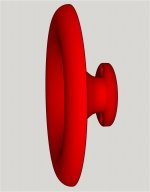
Comparing these to prior results with Sandhorn, I would like to try your round horn, assuming its terminating in a baffle instead of rolled back. I hope that is not too much trouble. Surrounding the waveguide with small drivers does seem to solve the CTC problem and the round wg seems to do it better, although the sandhorn isn't a fair or accurate test given its rollback.
Jack
PS wrong thread is what I get for trying to respond via my phone while watching TV 🙂
Very nice results popping up here... Sort of like a synergy horn without having to use the in horn entrances. Just close enough to the horn and array like mounting of those mids could be sufficient to steer the results at will.
You are good with CAD which is half the battle with ABEC/AKABAK. If you can make a simple model of the array cabinet, roundover, vanes and cone profile then I can help you simulate it. Quarter symmetry helps a lot with solving time so making it symmetrical is worth while. You have most of it done already, up to you if you want to give it a go. Just don't make the vanes too thin or the mesh will have to be dense to cover it.
The diaphragm can be simulated from a CAD drawing made into a mesh or via the diaphragm tool, as you already have a good model the CAD might be better.
I haven't been doing any follow up on this yet, as I expect more troubles from vanes than they would solve. While it most certainly could make a (positive) difference, one would probably need 'absorbing barriers' as vanes to be useful. Having vanes that reflect themselves wouldn't be helpful.
If you guys want to learn I can help you. Have a look at the video I posted in my ABEC thread that I found, he has now posted one on ABEC too.
Akabak might be better to start with as everything can be done through point and click. ABEC needs scripts which are not difficult once you understand what the elements do.
I can post some scripts and explain what the various sections means if you want that, but please remember that explaining something takes a lot more time that doing it 😉
I appreciate the offer. Not ready to go fully at it right now. I think I'll stick to first making my latest tweaks, while trying to come up with clever ways to improve the vertical spray situation. I'm hoping to be able stick to full range array and not having to resort to need central tweeters.
I can always sim a driver in Vituixcad that has different patterns horizontal vs vertical to see what happens. I'm pretty sure it would have an effect.
ABEC can be of use there if I could come up with a different baffle to limit the vertical directivity. (where the vanes are part of the baffle)
Here you go, if you think a smaller guide is worth trying I might something suitable already cooked.I would like to try your round horn, assuming its terminating in a baffle instead of rolled back. I hope that is not too much trouble.
I think I prefer the 800Hz or 1000Hz from above. The change in directivity is smoother. I don't target something that jumps from one to another even if it's better over some of the range.
Attachments
Sometimes these assumptions turn out to be wrong, so now I just give it a go and see what happens 😀I expect more troubles from vanes than they would solve. While it most certainly could make a (positive) difference, one would probably need 'absorbing barriers' as vanes to be useful. Having vanes that reflect themselves wouldn't be helpful.
I understand that you want to stick to the format you already have and with all the work you put in I can sympathise. Making the best from what you have is one of your Hallmarks. There's no time limit on the offer if you get curious 😉I appreciate the offer. Not ready to go fully at it right now. I think I'll stick to first making my latest tweaks, while trying to come up with clever ways to improve the vertical spray situation. I'm hoping to be able stick to full range array and not having to resort to need central tweeters.
Here you go, if you think a smaller guide is worth trying I might something suitable already cooked.
I think I prefer the 800Hz or 1000Hz from above. The change in directivity is smoother. I don't target something that jumps from one to another even if it's better over some of the range.
Thanks. What is the diameter?
I'd like to have the shape in Sketchup for visualization and fit. All it takes is a profile line to rotate but importing a curve is difficult unless you can find a plug in. I've imported one of mabat's stl's but its got so many triangles and squares it brings the program to its knees. If I delete all the shapes except a single profile line, I'll have what I want.
I agree on the 800 Hz. That is the widest vertical window and its not at all clear that that light red widening near 2 khz hurts anything.
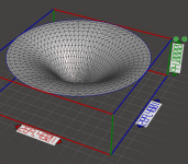
The diameter is 289.4801mm 😀
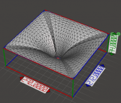
As you see from the wireframe this is circular but not axisymmetric the vertical beamwidth is narrower than the horizontal.
I can send you the whole thing as a step file if you can import that, rotating a profile won't work because it's not the same all the way round.

As you see from the wireframe this is circular but not axisymmetric the vertical beamwidth is narrower than the horizontal.
I can send you the whole thing as a step file if you can import that, rotating a profile won't work because it's not the same all the way round.
Attachments
Sorry if I sounded like teacher telling you off, your images are worth looking at so I do click on them but I hate having to keep going back in the browser 🙂Will do Duncan, thanks for the tip.
- Home
- Loudspeakers
- Full Range
- Full range line array for wall or corner placement