@fluid
thanks for that offer of help and also for posting the woofer above ground simulation. I wanted to see if those results correlated with Vituix simulated directivity and ground reflection but having tried, I realize it doesn't present the data the same way. But on 2nd thought it might work if I go back to the diffraction model and include the ground reflection there. What is the woofer height above ground in your sim?
thanks for that offer of help and also for posting the woofer above ground simulation. I wanted to see if those results correlated with Vituix simulated directivity and ground reflection but having tried, I realize it doesn't present the data the same way. But on 2nd thought it might work if I go back to the diffraction model and include the ground reflection there. What is the woofer height above ground in your sim?
Here is what Vituix showed me for a 12FH530 placed 300mm above perfectly reflecting ground.

Including the floor reflection in the synthesized directivity allowed me to see axial response and directivity charts that include it. That seems pretty useful!
Including the floor reflection in the synthesized directivity allowed me to see axial response and directivity charts that include it. That seems pretty useful!
Attachments
Re'
If the only free field limit is the floor, why did also horizontal show the same dip as vertical?
because the floor is still there regardless of which way the mic is moved. The reflection path length is relatively constant for horizontal angle changes so dip stays in same place. The reflection distance changes strongly for vertical chart so dip moves with angle
(for some reason TNTs original post doesn't appear except in my notification email)
gmail I think has a several seconds delay to allow you to unsend an email; sometimes its not enough for me
Better think ahead - I'll try to improve 🙂
Interesting insight is that it only takes 1 surface to spoli the party. And yet, there are typically 5 more ;-D
Oops, I did it again...
//
Interesting insight is that it only takes 1 surface to spoli the party. And yet, there are typically 5 more ;-D
Oops, I did it again...
//
I can run ATH through the STL generation step but I've had no luck with AKABAK translation of ATH ABEC scripts. Hopefully, I just need a little help getting started.
Have a look here for some information from DonVK and a test script, in case it is hard to see it is the semicolon separator between terms that is causing the issue
Acoustic Horn Design – The Easy Way (Ath4)
First help though is finding that link to a video in your thread, search tool didn't help, nor did a quick scan through the thread. Google search for ABEC turns up Swiss ball bearings used in inline speedskating, which I used to do 🙂
Here are some links
Simulating Waveguides in Akabak - YouTube
Here is the channel that has two other worthwhile videos
Austin Mys - YouTube
And the official ones
AKABAK - Videos
The center of the 15" woofer is 580mm above the infinite baffleWhat is the woofer height above ground in your sim?
What is interesting is that more sources and more surfaces smooths out the response. A single source and a single reflection is the worst case scenario from an optical point of view.Interesting insight is that it only takes 1 surface to spoli the party. And yet, there are typically 5 more ;-D
Thanks. I had eyeballed the height at 600mm
re' single source being wc = I've never seen combing as bad as Vituix shows it in its room response curve!
re' single source being wc = I've never seen combing as bad as Vituix shows it in its room response curve!
Here is the link to the ABEC Pro download page that mabat has on his Ath page. You should be able to download it from there if you want to. I don't know if the pro version works in demo mode without a release code but it should be easy enough to find out.
ABEC3 - Professional Version
ABEC3 - Professional Version
I think that is how Mabat is using it. I'll see...
However, as is the case every other time I've started to dig into ABEC, I've been distracted delayed by a more pressing idea. However, in this case, its one that motivates me to master ATH and ABEC
However, as is the case every other time I've started to dig into ABEC, I've been distracted delayed by a more pressing idea. However, in this case, its one that motivates me to master ATH and ABEC
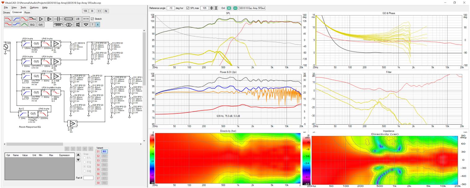
I think perhaps I've finally got the expanding array with waveguide at center right, or close to right.
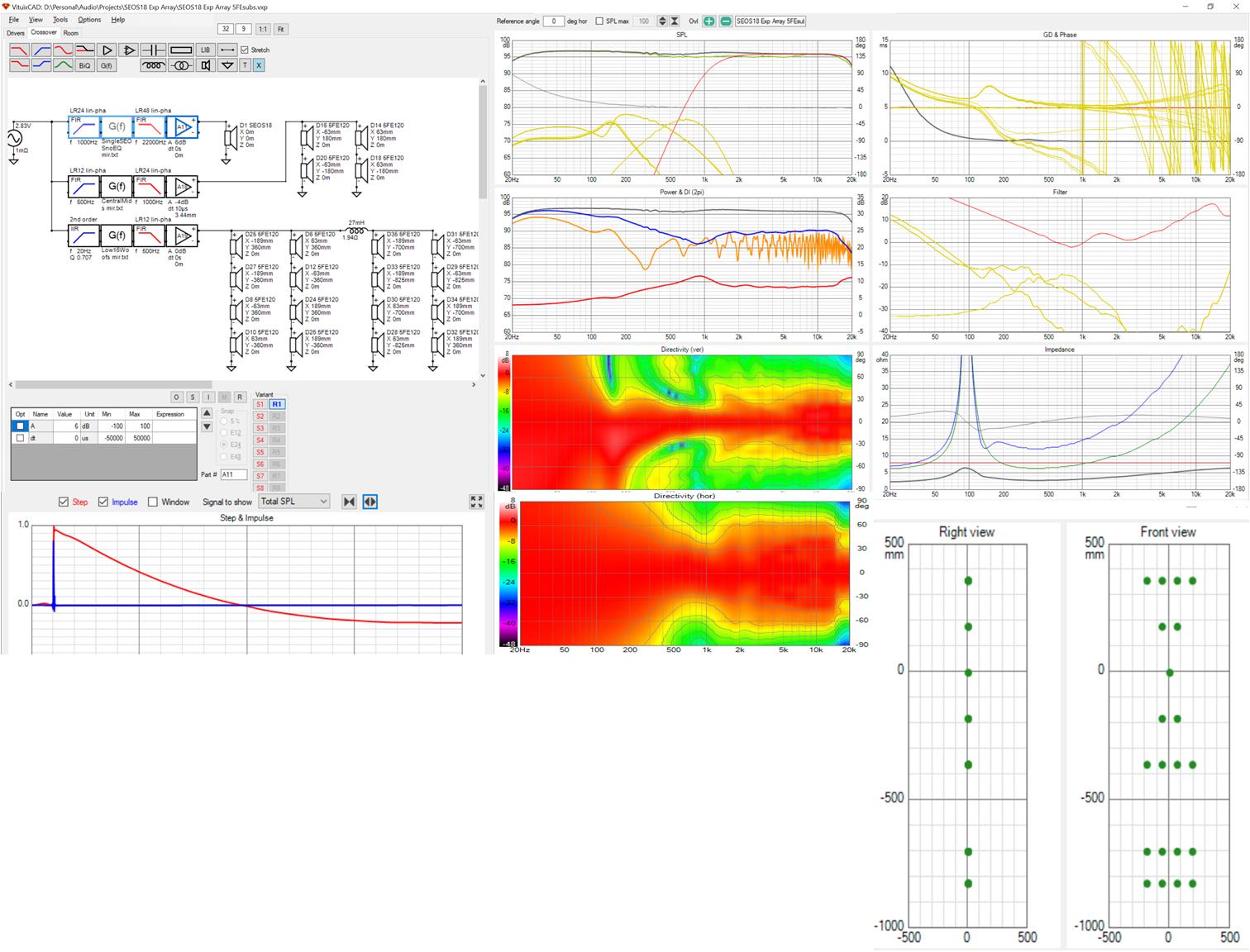
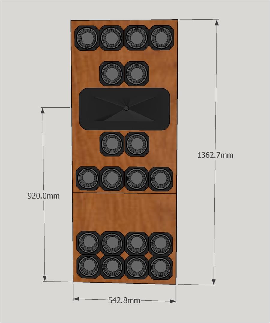
The screenshot tells most of the story. The waveguide is the SEOS18, of which I have a pair in storage, and whose directivity I was able to trace. The central 5FE120s act as bridge drivers between the CD and the outer top midwoofers, covering just 500 Hz to 1 kHz. I have XO at 1 kHz but it could be as high as 1500 Hz or even 2 kHz. 8 more midwoofers near the floor provide enough displacement to extend down to 20 Hz for in home use.
The piece of the puzzle I had been missing was to make the array wider as well as it expands in height, choosing to the mids before the wg completely loses pattern control. Driver position adjustments and SPL balance among groups make all the difference. The room response ripple and combing are primarily due to the floor and secondarily to the ceiling. The wg does a good job of keeping the sound off the walls. They have almost no effect other than to support the bass.
In the simulation, I have all four boundary surfaces enabled for reflections with the array tight into a corner toed in 45 degrees.
the cabinet needs only about 1L per 5FE120 and so can be quite thin, if you allow the WG and CD to stick out the back. In my musings I was first going to package it as a top for my AE TD15H corner woofers. When that ended up looking too much like a refrigerator, I decided to make it as narrow and thin as possible so it could nestle more deeply into a corner and perhaps someday find a home in my living room.
Here is my current Sketchup concept. Ifs about 180mm deep +/- depending on the CD:
Attachments

Of course I spent the rest of the day tweaking the design so now I need to repost.
First, here is rendering that will put it in perspective. The array in a corner with 9' ceiling:
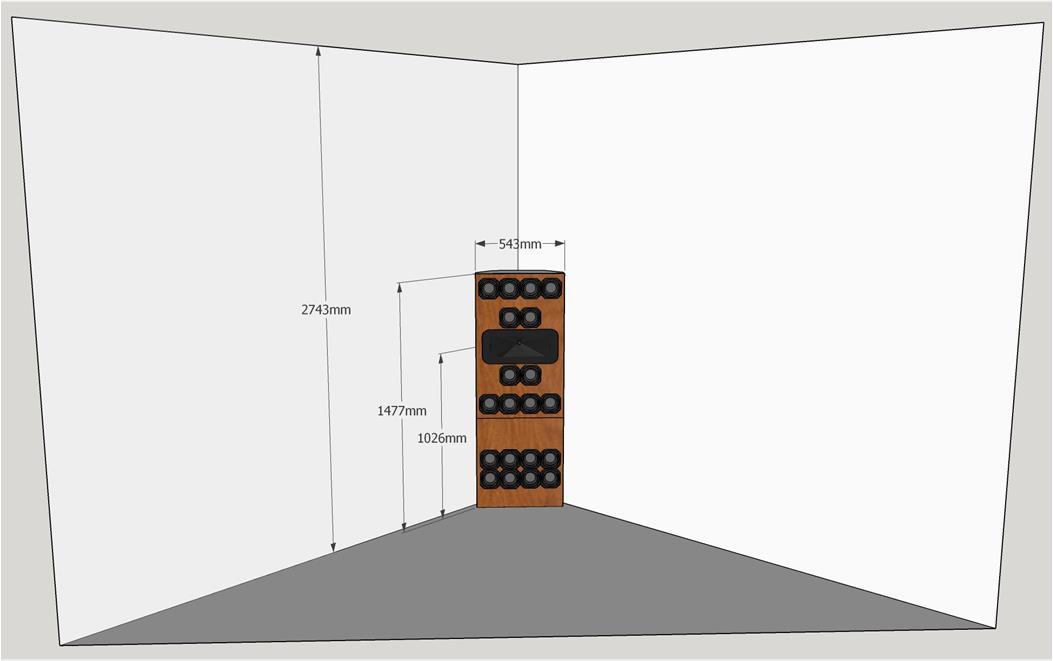
Its not visually imposing and if I could get directivity files for SEOS12, I could likely shrink the width by a third!
First, here is rendering that will put it in perspective. The array in a corner with 9' ceiling:
Its not visually imposing and if I could get directivity files for SEOS12, I could likely shrink the width by a third!
Attachments

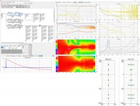
The primary reason for my changes was a floor null at ~300 Hz that snuck in when I tried a passive XO to the lowest woofers to save an amplifier. Abandoning that and going back to full active, I arrived here:
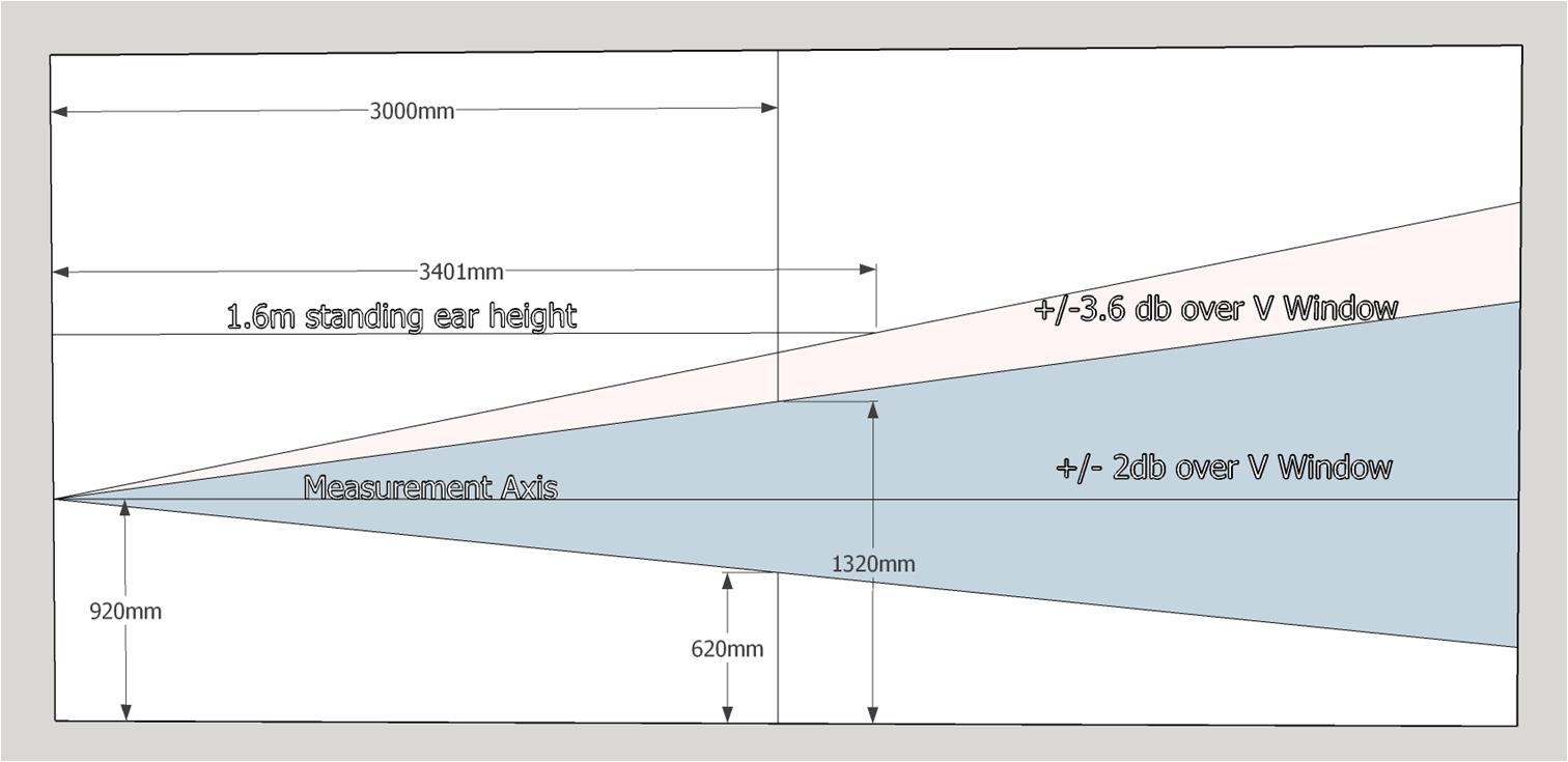
The other significant change was to raise the drivers 100mm while keeping the mic height at 920mm. This centered the vertical window at the mic height. The polar charts look impressively good. The horizontal pattern control has been extended down to about 400 Hz with a small narrowing. The vertical chart is the best I've seen for an array of this type.
But as good as they and the corresponding line charts are, the simulated room responses still show some variation. All of that is summarized below:
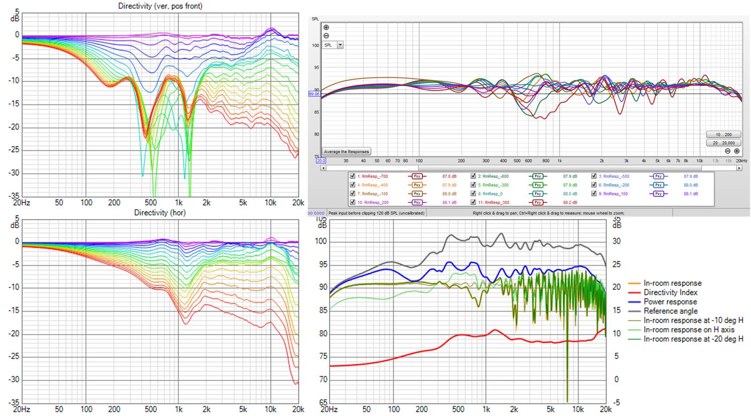
Sketchup did the trig to show the vertical window on the horizontal axis:
After doing this on axis, I checked off axis responses. The measurements shown are with a ref angle of -10 degrees. The overlays in the Vituix chart below the REW screenshot show a big response drop going back on axis but very small change continuing out to -20 degrees.
The floor has a very strong effect on the response. I speculated that stacking another woofer/subwoofer module on top might reduce the response variation with height. I was actually happy to find that it didn't make a significant difference.
The other significant change was to raise the drivers 100mm while keeping the mic height at 920mm. This centered the vertical window at the mic height. The polar charts look impressively good. The horizontal pattern control has been extended down to about 400 Hz with a small narrowing. The vertical chart is the best I've seen for an array of this type.
But as good as they and the corresponding line charts are, the simulated room responses still show some variation. All of that is summarized below:
Sketchup did the trig to show the vertical window on the horizontal axis:
After doing this on axis, I checked off axis responses. The measurements shown are with a ref angle of -10 degrees. The overlays in the Vituix chart below the REW screenshot show a big response drop going back on axis but very small change continuing out to -20 degrees.
The floor has a very strong effect on the response. I speculated that stacking another woofer/subwoofer module on top might reduce the response variation with height. I was actually happy to find that it didn't make a significant difference.
Attachments

This array has a very Synergy-like response in its wide vertical window. It would be interesting to compare them. I would expect less variation anechoically but more when floor reflections are brought in.
The close in woofers are at a CTC of 180mm. The XO ended up at 1250 Hz, which has a wavelength of roughly 275mm. CTC = .65 wavelength at XO. Its nice to be able to get this kind of response without going to the trouble of making a MEH.
The other benefit of this approach is the extension of vertical pattern control from somewhere around 2 khz where the wg begins widening down to about 300 Hz. Ask Mark100 how big a Synergy horn has to be for the same pattern control.
This is really interesting! A flat board is certainly much easier than a MEH. I follow with interest🙂 Is there any reason why you want to use the SEOS12?
The other benefit of this approach is the extension of vertical pattern control from somewhere around 2 khz where the wg begins widening down to about 300 Hz. Ask Mark100 how big a Synergy horn has to be for the same pattern control.
Whoa ! 300Hz vertical control, nice 🙂
If I understand the directivity plots correctly, I think it would take a Synergy about 42" tall to do that.....yikes !
But let me make sure i know how to read the plots, so please help me with some very basic questions...
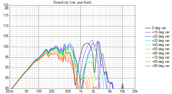
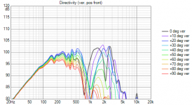
Looking at this snip from #813,

The Vertical's contour line at the edge of red, at 300Hz looks to be at +30 and -30 degrees. Also looks to be about a -6dB contour.
Is that correct?
Hope so for conformity, because prosound pattern control specs, HxV are almost always defined by the -6dB contour....(at what frequency however is always the hidden issue and often BS in such a simple spec, huh)
Anyway, if correct, the vertical has a '60 degree pattern' down to 300Hz, yes?
Again, wow.
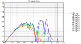
What would you call the horiz pattern?
Looks to me about 90 degrees from about 3k to 15kHz, and a bit narrower, say 60 degrees at 300Hz.
Again, just making sure I'm reading the graphs correctly, and in sync with regard to quoting pattern control, and matching up to BWaslo's sheet.
The SEOS18 is a 90H x 60V horn and that is the pattern above XO. Those are 6db contour lines. Sorry for covering the axis labels.
Mabat just published measurements for his first 13" dia. axisymmetric sandhorn. I placed 12 TC9s around it with rims just touching the wg to tell if this technique works for a round waveguide and apparently it does! The 12 TC9's should cover down to 100 Hz so you can mount the ensemble freestanding or on top of a sub. You shouldn't try to do this with a rolled back edge waveguide like he printed but for one designed to terminate in a baffle.
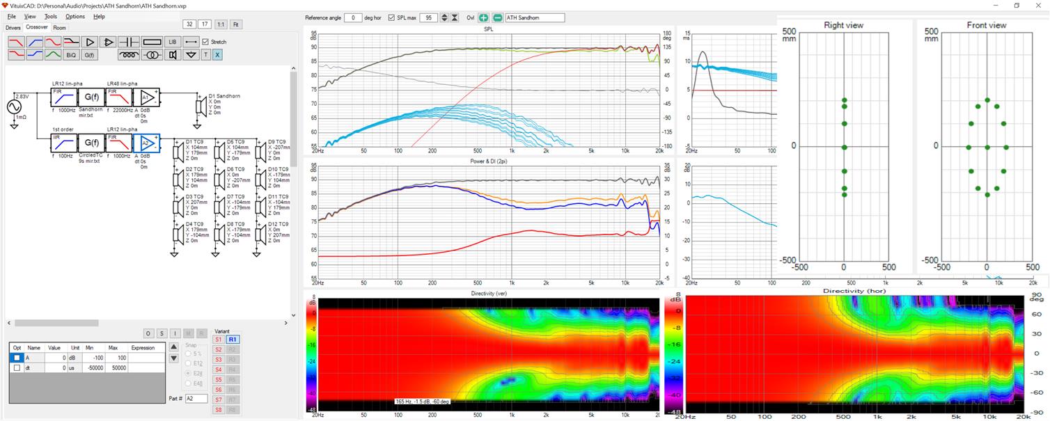
No reflections in this response. Just verifying a nice clean XO and pattern control extension.
No reflections in this response. Just verifying a nice clean XO and pattern control extension.
Attachments
- Home
- Loudspeakers
- Full Range
- Full range line array for wall or corner placement