Floor Bounce Cancellation ???
Its hard to ignore the good work being exhibited in the ATH thread. With waveguides like that now do-able, my thoughts return to Unity/MEH. The problem with full range point sources is that, unless the source is inside a very large horn, there is going to be significant floor bounce. Can the floor bounce be cancelled or is it better to add beam forming drivers above and below the waveguide to increase the vertical directivity.
Here is my try at cancelling floor bounce. I want to send a signal from a woofer below my reasonable sized Unity horn, that is equal in amplitude and opposite in phase to the wave reflected from the floor, at least over the range of the lowest cancellation null. For this experiment, I'm setting the phase according to calculated path length difference and eyeballing the amplitude and frequency response of the cancellation wave. The two DSP paths are summed in the driver in the sim; in the real world they could be summed earlier, e.g. in the mixer of my 8 ch MOTU sound card.
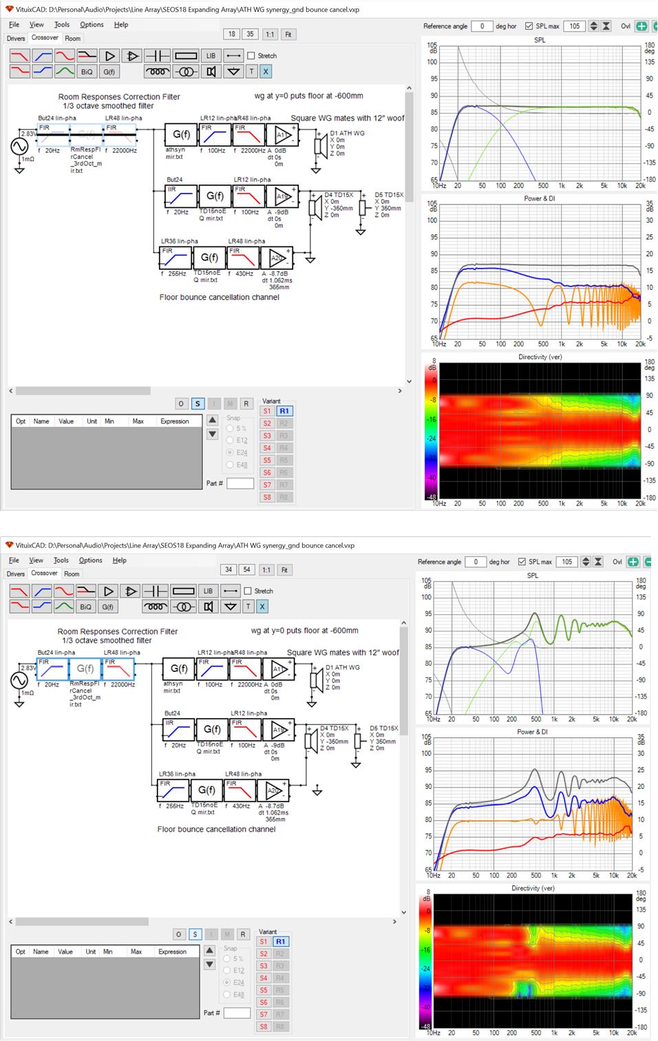
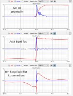
The top screen shot is without cancellation. Since its simulation, I can short the output of the amplifier to disable cancellation. The direct wave is equalized flat.
The bottom screen shot is with the cancellation channel connected and the room response equalized flat. The first floor bounce null is gone and all it cost me, besides the additional dsp channel is a narrowing of the vertical directivity near the floor bounce null. That is pretty neat. I wish I could listen to it. I've always wondered how audible a floor bounce null is.
The idea seems to work in simulation to a decent extent. I see two issues; one being that cancellation only works at one spot and two that the cancellation signal will also beat with the direct wave. Fortunately, the direct path length and cancellation path lengths are not very different:
direct path 3500 mm
refl path 3891 mm
cancel path 3517 mm
delta path 0374 mm
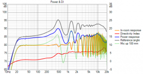
but things fall apart with just 100 mm of mic/head movement:

So much for cancellation 🙂
Its hard to ignore the good work being exhibited in the ATH thread. With waveguides like that now do-able, my thoughts return to Unity/MEH. The problem with full range point sources is that, unless the source is inside a very large horn, there is going to be significant floor bounce. Can the floor bounce be cancelled or is it better to add beam forming drivers above and below the waveguide to increase the vertical directivity.
Here is my try at cancelling floor bounce. I want to send a signal from a woofer below my reasonable sized Unity horn, that is equal in amplitude and opposite in phase to the wave reflected from the floor, at least over the range of the lowest cancellation null. For this experiment, I'm setting the phase according to calculated path length difference and eyeballing the amplitude and frequency response of the cancellation wave. The two DSP paths are summed in the driver in the sim; in the real world they could be summed earlier, e.g. in the mixer of my 8 ch MOTU sound card.
The top screen shot is without cancellation. Since its simulation, I can short the output of the amplifier to disable cancellation. The direct wave is equalized flat.
The bottom screen shot is with the cancellation channel connected and the room response equalized flat. The first floor bounce null is gone and all it cost me, besides the additional dsp channel is a narrowing of the vertical directivity near the floor bounce null. That is pretty neat. I wish I could listen to it. I've always wondered how audible a floor bounce null is.
The idea seems to work in simulation to a decent extent. I see two issues; one being that cancellation only works at one spot and two that the cancellation signal will also beat with the direct wave. Fortunately, the direct path length and cancellation path lengths are not very different:
direct path 3500 mm
refl path 3891 mm
cancel path 3517 mm
delta path 0374 mm
but things fall apart with just 100 mm of mic/head movement:
So much for cancellation 🙂
Attachments

So cancellation is too position dependent. Let's see if floor bounce nulls can be mitigated by overlapping a Synergy horn with a woofer in the 200 Hz to 600 Hz region where the lowest such nulls typically occur.
Here is my design. The waveguide is an early ~12" square one whose polars were posted in the ATH thread as line charts and which I traced in Vituix. It is at 1m high and the 15" woofer sits at/near floor level. The hump in the axial response is flattened by the global eq which was disabled for the screenshot to show the overlap. I'm doing this eq with Vituix mirroring. RePhase has overlap XO filters that might work better but I haven't tried them here (yet).
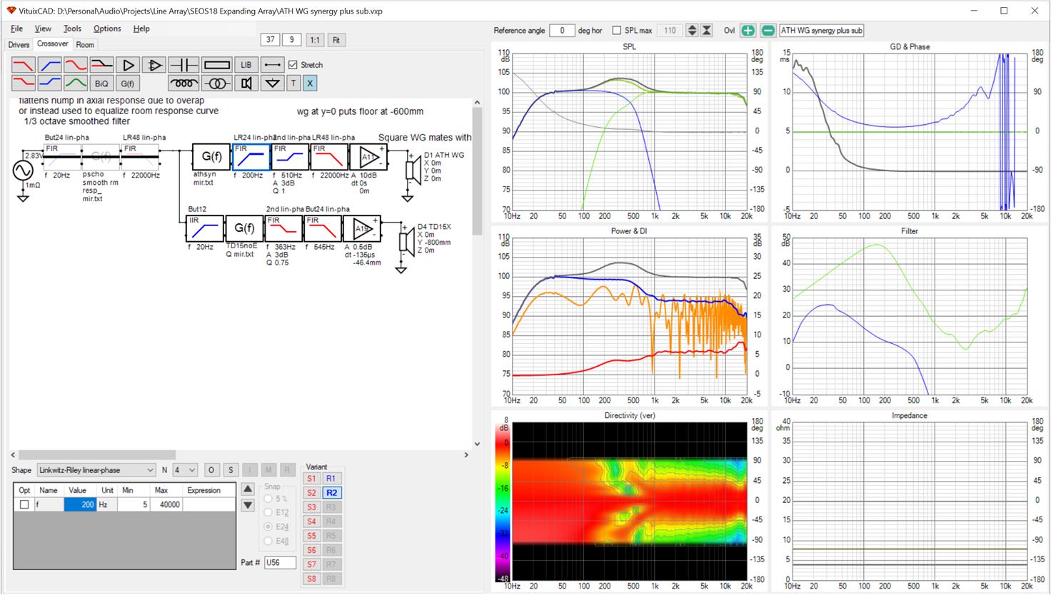
Note the narrowing of the vertical polars in the overlap region. This is caused by the interference nulls. The nulls can be steered by varying delay on the woofer. I have adjust delay to center the narrow vertical window at the nominal 1m listening height and verified I can move it above or below that axis with the delay. This is important as my listening height varies with which chair I select.
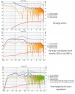
The effectiveness of the overlap in mitigating floor bounce is evident below.
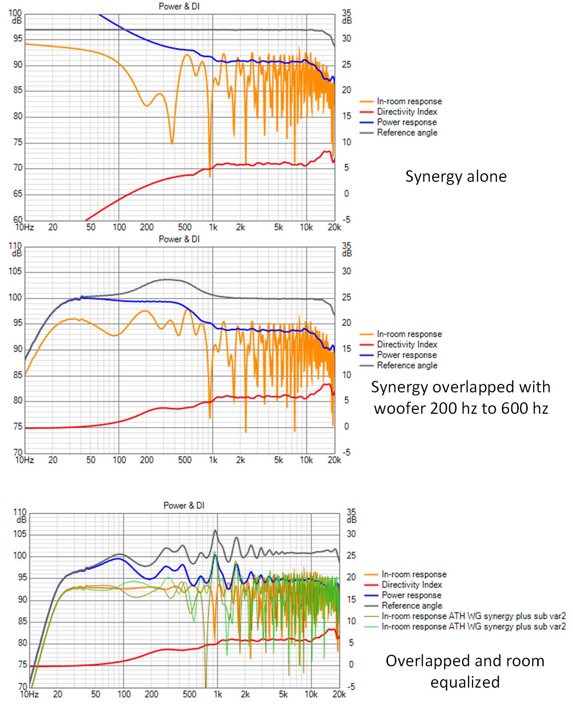
The top graph is the Synergy playing alone with the overlap filters disabled for a flat axial response. The floor bounce null would definitely be audible. The narrow combing nulls at higher frequencies likely wouldn't be audible.
the middle graph is with both drivers overlapped but without global EQ. The situation is much improved!
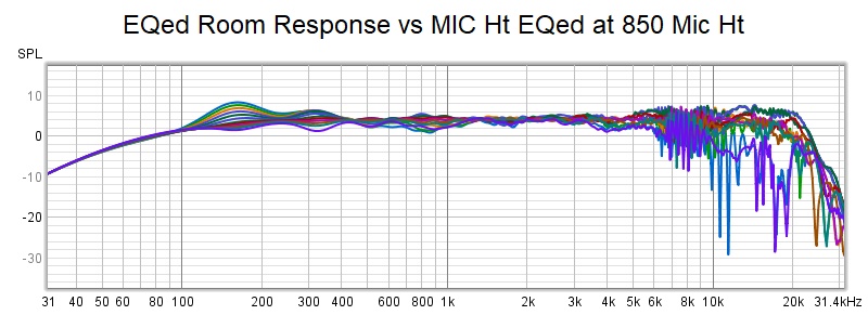
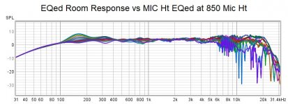
The bottom graph is with the room response equalized. I exported the simulated room response to REW, applied pyscho-acoustic smoothing and brought back into Vituix for mirror equalization. The two traces overlaying the resulting room response are with the mic moved up and down 100 mm.
This would seem to be effective for seated only listening. The response can be tuned to a specific ear height with delay on the woofer. It seems that if one wants a really tall listening window, a larger horn/waveguide is required, or a line array.
Here is my design. The waveguide is an early ~12" square one whose polars were posted in the ATH thread as line charts and which I traced in Vituix. It is at 1m high and the 15" woofer sits at/near floor level. The hump in the axial response is flattened by the global eq which was disabled for the screenshot to show the overlap. I'm doing this eq with Vituix mirroring. RePhase has overlap XO filters that might work better but I haven't tried them here (yet).
Note the narrowing of the vertical polars in the overlap region. This is caused by the interference nulls. The nulls can be steered by varying delay on the woofer. I have adjust delay to center the narrow vertical window at the nominal 1m listening height and verified I can move it above or below that axis with the delay. This is important as my listening height varies with which chair I select.
The effectiveness of the overlap in mitigating floor bounce is evident below.
The top graph is the Synergy playing alone with the overlap filters disabled for a flat axial response. The floor bounce null would definitely be audible. The narrow combing nulls at higher frequencies likely wouldn't be audible.
the middle graph is with both drivers overlapped but without global EQ. The situation is much improved!
The bottom graph is with the room response equalized. I exported the simulated room response to REW, applied pyscho-acoustic smoothing and brought back into Vituix for mirror equalization. The two traces overlaying the resulting room response are with the mic moved up and down 100 mm.
This would seem to be effective for seated only listening. The response can be tuned to a specific ear height with delay on the woofer. It seems that if one wants a really tall listening window, a larger horn/waveguide is required, or a line array.
Attachments

look at a 2 way
Before I congratulate myself, I should look at a 2 way without overlap; 1 12" wg above and as close as possible to a 12" woofer. The resulting CTC is 300mm, which may be a little optimistic. I estimate using a high aspect rectangular conical horn slot woofer only 100mm tall, CTC can be reduced to 200 mm and horizontal directivity match maintained. I will compare the two.
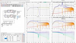
Here is the Vituix screenshot with results for both.
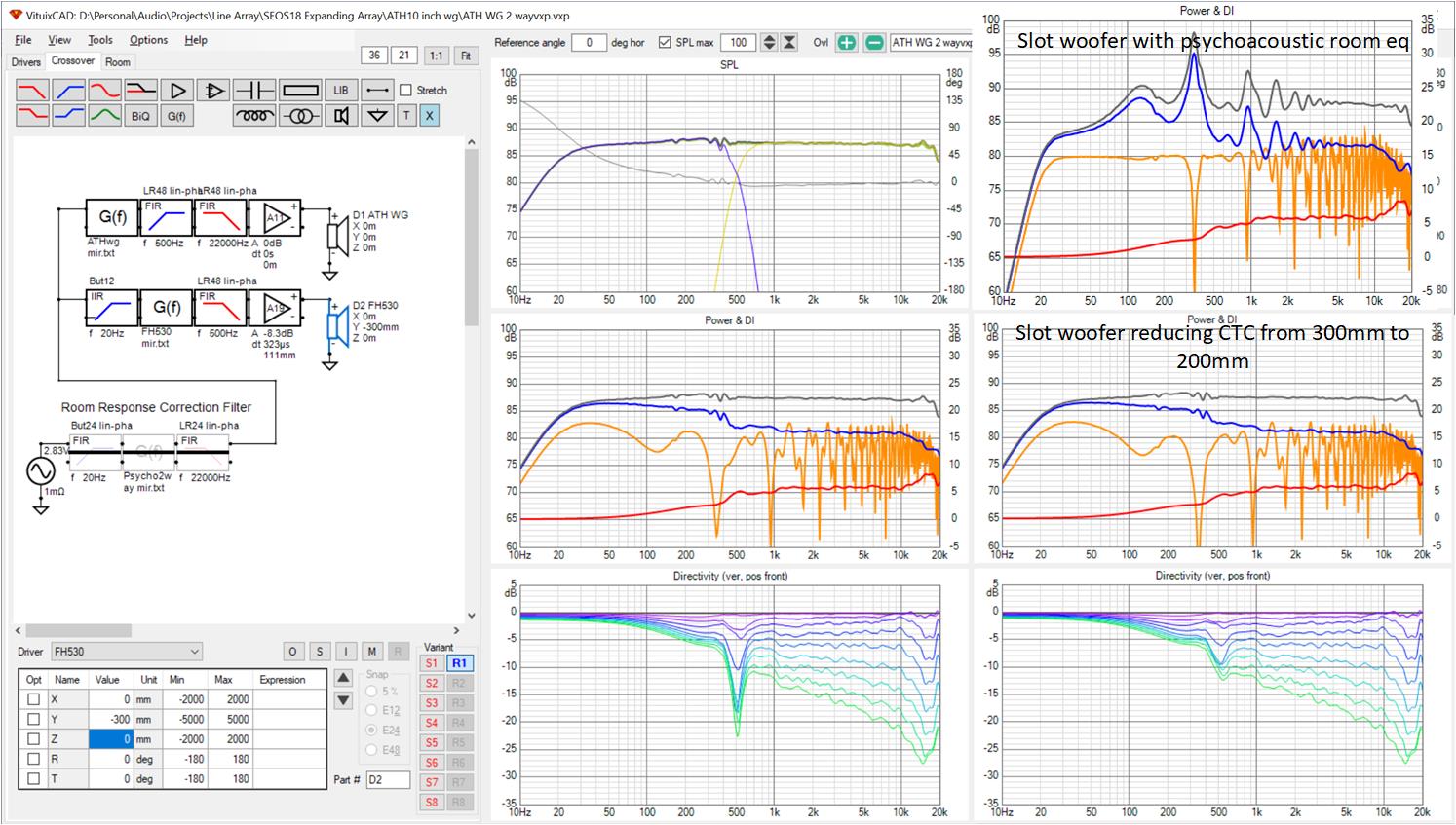
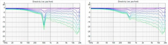
Compare the round vs slot vertical directivity line charts. The slot doesn't have the severe narrowing in vertical response near the 500 Hz XO.
The floor bounce in the room response for the two isn't much different. This is true with or without EQ to the psychoacoustically smoothed room response, although I only show the EQed response for the slot. The narrowness of the remainining nulls are arguably inaudible.
Its not until I investigate the equalized room response vs vertical offset that I see a difference not between round and slot but between the two way and the previous Synergy overlapped with a woofer.

Once off EQ height by just 100 mm, degradation is significant. The Synergy with overlapped woofer is better in this regard.
Before I congratulate myself, I should look at a 2 way without overlap; 1 12" wg above and as close as possible to a 12" woofer. The resulting CTC is 300mm, which may be a little optimistic. I estimate using a high aspect rectangular conical horn slot woofer only 100mm tall, CTC can be reduced to 200 mm and horizontal directivity match maintained. I will compare the two.
Here is the Vituix screenshot with results for both.
Compare the round vs slot vertical directivity line charts. The slot doesn't have the severe narrowing in vertical response near the 500 Hz XO.
The floor bounce in the room response for the two isn't much different. This is true with or without EQ to the psychoacoustically smoothed room response, although I only show the EQed response for the slot. The narrowness of the remainining nulls are arguably inaudible.
Its not until I investigate the equalized room response vs vertical offset that I see a difference not between round and slot but between the two way and the previous Synergy overlapped with a woofer.
Once off EQ height by just 100 mm, degradation is significant. The Synergy with overlapped woofer is better in this regard.
Attachments

When I look at the side by side graphs of vertical directivity I think it shows that within a reasonable listening window there is a dB or two at most between them. It gets deeper further off axis but also over a smaller range. Whilst a compromise on perfection in reality the audibility would be low.

Attachments
That is what I said, more or less, but I also pointed out that the prior sim - synergy overlapped with a woofer in the lowest floor bounce null region was significantly better in this regard.
Its surprising to me how positionally sensitive these room response EQs are. That might call for EQ to an average of multiple measurements even over a small range of heights.
Its surprising to me how positionally sensitive these room response EQs are. That might call for EQ to an average of multiple measurements even over a small range of heights.
Yes I see what you were getting at now, sometimes the big image displays with multiple options can pass me by.but I also pointed out that the prior sim - synergy overlapped with a woofer in the lowest floor bounce null region was significantly better in this regard.
Multiple vertical sources are particularly good at mitigating the floor bounce and smoothing that region.
Now I need to think more seriously about getting smaller woofers in the horn and keeping the big woofers below but further down 🙂
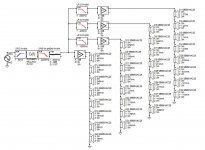
Today I'm back to my own line array considering implement coarse frequency shading via DSP using my 8x125W amplifier and JRiver. To do this, I have to rewire the array into a different set of 4 groups of 8, than their current wiring. Never mind that for now.
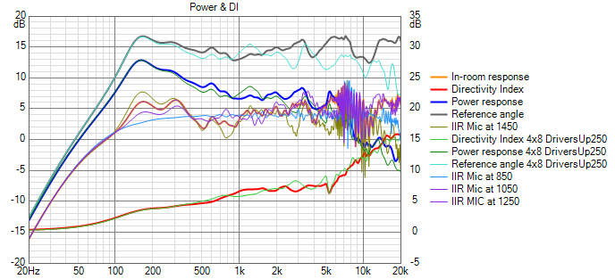
Doing this I discovered vertical response window is much wider if I elevate the array above the floor by 250 mm. This seems to be an optimum and it doesn't matter if I model the room as 8' or 9' ceiling height.
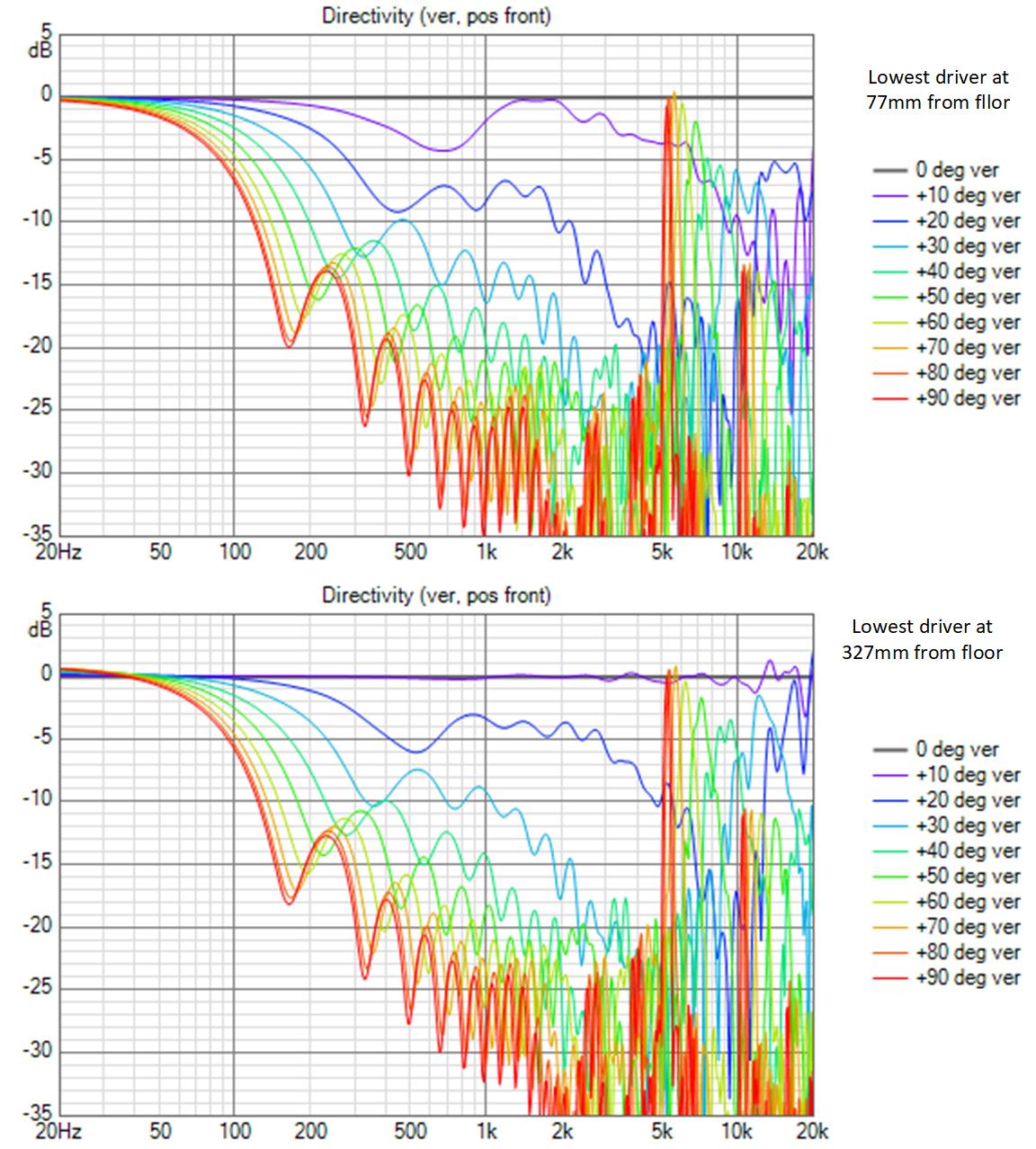
With the drivers repositioned higher, the 10 degree line is almost totally flat. 10 degrees from the elevated array center includes my standing height at 3m listening distance!
Doing this I discovered vertical response window is much wider if I elevate the array above the floor by 250 mm. This seems to be an optimum and it doesn't matter if I model the room as 8' or 9' ceiling height.
With the drivers repositioned higher, the 10 degree line is almost totally flat. 10 degrees from the elevated array center includes my standing height at 3m listening distance!
Attachments
Yes this is a surprising result. Its also surprising that it makes such a big difference. I don't understand why the optimum is where it is....
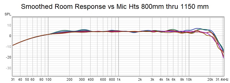
Here is what I get equalizing the room responses. These responses show combing in the 7-10 khz region due to floor and ceiling reflections. The Vituix mirror eq gets thrown off by that combing; thus that hump in that region. I applied psychoacoustic smoothing in REW so we could see what was behind the combing.
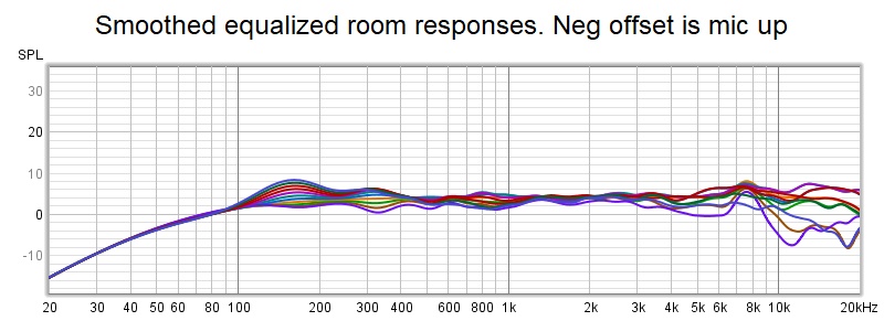

unsmoothed view with mic at array center moved to seated ear height

unsmoothed view with mic at array center moved to seated ear height
Attachments

It does seem to good to be true but it has held up to re-examination.
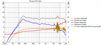
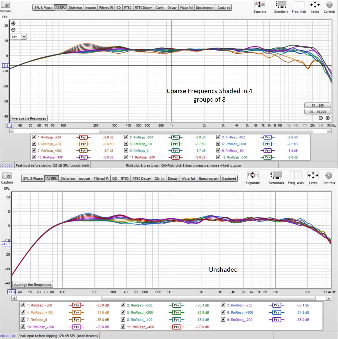
to remind myself why I'm doing this, I compared shaded to unshaded:
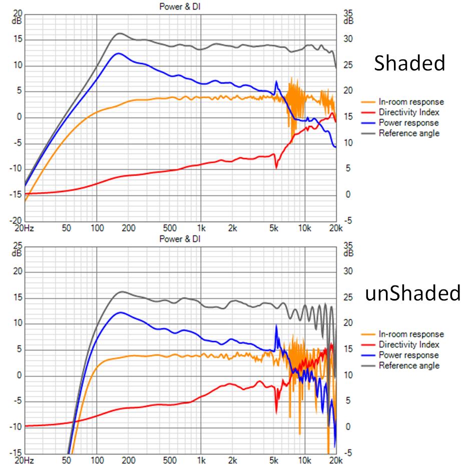
shading takes care of the combing on the direct beam. what remains is almost entirely due to the delayed floor and ceiling reflections; more floor than ceiling at the high end because of beaming together with higher angles needed to hit ceiling in spot where reflection hits mic.
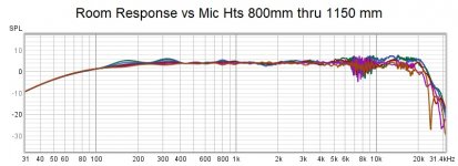
I replotted the response vs offset labelled with mic elevations
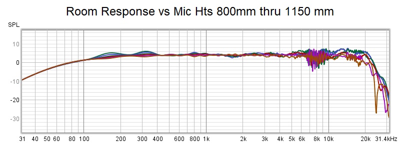
The range on this one is 650mm to 1550 mm
I'm reminded that screenshots of REW are better...
to remind myself why I'm doing this, I compared shaded to unshaded:
shading takes care of the combing on the direct beam. what remains is almost entirely due to the delayed floor and ceiling reflections; more floor than ceiling at the high end because of beaming together with higher angles needed to hit ceiling in spot where reflection hits mic.
I replotted the response vs offset labelled with mic elevations
The range on this one is 650mm to 1550 mm
I'm reminded that screenshots of REW are better...
Attachments

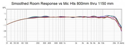
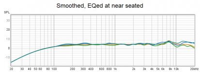
comparing shaded to unshaded we see shading reduces the vertical window as treble falls off when mic is too far above or below the central group of 8 drivers that is driven full range.
these responses are smoothed so the differences in combing is masked. It was shown a few posts earlier
these responses are smoothed so the differences in combing is masked. It was shown a few posts earlier
Attachments
That should give you a nice clean IR too. Just wondering if it would have worked with passive components...
Let me change the filters to IIR and see what happens. The first thing I saw was a sharp dip around 16 khz due to IIR filter group delay. I compensated this with 20 usec in the center group, re-EQed, and tried some offsets. Its not nearly as good.
Its clear that the difference in response between LinPhase and IIR/passive filters is due solely to the group delay of the IIR filters. Its conceivable one could do a biamp solution with DSP group delay compensating filter on the central group and a second amp feeding the other 3 groups through passive filters. That group delay compensating filter could be designed in RePhase manually moving sliders
Its clear that the difference in response between LinPhase and IIR/passive filters is due solely to the group delay of the IIR filters. Its conceivable one could do a biamp solution with DSP group delay compensating filter on the central group and a second amp feeding the other 3 groups through passive filters. That group delay compensating filter could be designed in RePhase manually moving sliders
Attachments

Last edited:
Here is the schematic of whose responses I've been showing
Hi Jack, great work...always following along 🙂
Have you tried low passing the D9-D12 & D21-D24 sections at something lower than 13.2k ?
Like say 8k? I'm just asking, wondering if that might change combing.
I have probably tried most everything by now 🙂
The next closest set of drivers has a compromise corner frequency[ too low and I lose treble off vertical axis too soon, too high and more combing.
Initially I made as spreadsheet with the delta path length from each driver and worked out the frequency where that was 90 degrees phase shift and used that for the low pass corner. But while that rule totally eliminated combing and ripple on the direct beam, it also made the vertical window too narrow. I ended up where I am after a lot of detours. (understatement)
- Home
- Loudspeakers
- Full Range
- Full range line array for wall or corner placement