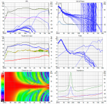
these responses are smoothed so the differences in combing is masked. It was shown a few posts earlier
Smoothed they (the unshaded array) do look hard to beat, don't they? I think that's what makes an (unshaded) array such a fascinating beast to listen to. At least I think so. While it still has it's flaws. They excel in the midrange because of that, where a lot of our music lives.
I went trough a lot of iterations just to keep that bundling round the "center line" effect in my attempts.
I see you're using second order low passes, that must be the biggest difference compared to what I have used. For me, I started with first order, I even introduced a sort of shelf function before rolling off their top end. Basically to get the smoothest vertical band I could get, within the constraints I worked with. This did mean using some interference, which was way more unpredictable than I wished it was...
Thanks, and pls pardon my casual, probably excessively naive question.
You know me, i have a hard time following sims, and fully appreciating all the hard work and investigative inspiration that goes into them 😱
No, that was a good question and on the right track but I had indeed tried what you had suggested - its so easy to do in simulation.
My former day job taught me to rely on simulations. We wouldn't dream of prototyping a chip without thorough sims (roomful of computers going 24x7 for months) verifying every aspect of functionality. This kind of simulation is more a quick and dirty virtual prototype to answer "what if" questions. These answers need to be confirmed by experiment, if the indication from simulation is positive - a step I'm going to have to move on to sooner or later.
Smoothed they (the unshaded array) do look hard to beat, don't they? I think that's what makes an (unshaded) array such a fascinating beast to listen to. At least I think so. While it still has it's flaws. They excel in the midrange because of that, where a lot of our music lives.
/QUOTE]
Yes indeed smooth, shaded does look and sound good. I went through all my old measurements of the arrays looking for polar responses yesterday to compare to these simulations and didn't find any. I do recall finding them equally pleasing sitting or standing. Perhaps that is why I never tried to measure the difference.
I'm sure you recall making the argument that combing isn't an issue for these arrays because it reduces with distance and its largely inaudible. I agree with that and I'm sure the latter part is true but not to what extent. What we are doing with shading is reduclng/eliminating that combing and with that the primary reason for trying a central tweeter.
But keep in mind that central tweeter would have greater combing from floor and ceiling reflections. The tweeter's wider dispersion is not a benefit in rooms as small as we have.
Its too bad shading also shrinks the vertical window (while reducing variation within that window); else you could use sharper slopes and get greater reduction of combing.
One of the next things I want to do is review the preference research and see what has been found about line arrays and the audibility of floor and ceiling reflection combing and nulls.
The combing at the top end is not audible in the way that it looks on a frequency response but making changes to the timing and frequency through impulse correction can result in a better perceived result for me. That makes me think that reducing/eliminating it could well be worthwhile but how much is very hard to say.
I don't think you will find much preference research including line arrays. The best studies on reflection audibility seem to be those from Soren Bech. Floor and ceiling being the worst offenders in terms of timbre change, a big part of the motivation for me to build arrays that addressed them.
The last few paragraphs of this article are quite relevant to this, Peter Lyngdorf and Art Noxon being interviewed
A round table about room acoustics, and bass traps.
The preference research seems to be about what frequency response sounds best than what kind of speaker design with that frequency response sounds best in a particular kind of space. Professional audio is about getting that response over many seats. DIY is about 1 to several seats, sometimes a larger HT.
Thanks for that link. I'm glad they endorse my search for a solution to floor and ceiling reflections which has brought me full circle to line arrays, since I don't have space for huge waveguides.
Thanks for that link. I'm glad they endorse my search for a solution to floor and ceiling reflections which has brought me full circle to line arrays, since I don't have space for huge waveguides.
I had an idea for the 2 way speaker CTC issue which in retrospect may explain why shifting my array shading relative to the vertical listening axis widened my vertical window.
Conventionally, we place the wg center at ear height and the woofer below resulting in a path length difference on the listening axis. If we shift the drivers upwards so they are centered about the vertical axis, path lengths are equalized on the listening axis. You can tilt the wg down to counteract beaming at hf.
The lobing at xo is best seen in Vituix using a polar chart at/near XO frequency
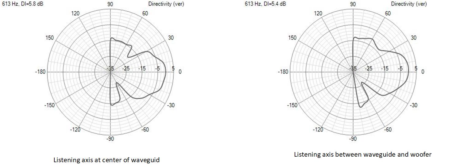
Judging where the main beam is down 1db, the beam width difference is 50%. At -3db or -6db points, the difference isn't nearly so large
Conventionally, we place the wg center at ear height and the woofer below resulting in a path length difference on the listening axis. If we shift the drivers upwards so they are centered about the vertical axis, path lengths are equalized on the listening axis. You can tilt the wg down to counteract beaming at hf.
The lobing at xo is best seen in Vituix using a polar chart at/near XO frequency
Judging where the main beam is down 1db, the beam width difference is 50%. At -3db or -6db points, the difference isn't nearly so large
Attachments
Last edited:
with the help of polar charts, I think I can explain the improvement in my vertical window with shifting drivers upwards.
To relate it to the previous post, think of the center, unshaded portion of the array as the waveguide/tweeter and the outer, shaded portions as woofers.
The main things that happen when I shift the entire array upward is shown below with polar chart at a random frequency.
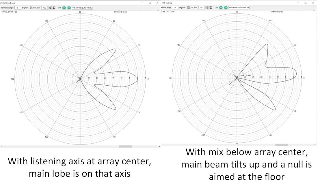
When I repositioned the array, I tilted the main beam of the array upwards and aligned the bottom edge of it with the bottom edge of my vertical listening window at my listening distance. For a different listening distance I would want a different vertical array position.
There is also less energy aimed at the floor than at the ceiling. I'm not sure how much that matters. The floor reflections are earlier but enabling/disabling floor reflections has a larger effect on the room response than doing that to ceiling reflections.
While the lobing pattern in the polar chart varies with frequency the two aspects noted are consistent with frequency.
To relate it to the previous post, think of the center, unshaded portion of the array as the waveguide/tweeter and the outer, shaded portions as woofers.
The main things that happen when I shift the entire array upward is shown below with polar chart at a random frequency.
When I repositioned the array, I tilted the main beam of the array upwards and aligned the bottom edge of it with the bottom edge of my vertical listening window at my listening distance. For a different listening distance I would want a different vertical array position.
There is also less energy aimed at the floor than at the ceiling. I'm not sure how much that matters. The floor reflections are earlier but enabling/disabling floor reflections has a larger effect on the room response than doing that to ceiling reflections.
While the lobing pattern in the polar chart varies with frequency the two aspects noted are consistent with frequency.
Attachments
For the tweeter addition to our line arrays, the ideas of bbutterfield's fractional array, or maybe even simpler, his more simplified 3-way as seen here: Skylark Flying Towers: Nested Array Speakers in Denovo Cabinet could serve as inspiration. Basically he used a single Fountek Neo X 2.0 sided with two TC9's acting like filler drivers, ala the Duelund filler driver principles.
I think there's some merit there, even if it still shows some side-banding, it won't be of the proportions that the center to center spacing of our drivers cause and are a way to get a better transition. That is if the tweeter has a wide enough vertical to serve our needs. Something to think about at least.
(well, after first enjoying the tweaks I have come up with so far and judging that for quite a while 😉)
I think his goals were similar to what we want to achieve here, for similar reasons as well.
(might as well use 2x Scan Speak 10F as the filler drivers for a bit more sensitivity for those two drivers that fill in the 800 Hz - 3 KHz,
though I'm sad to see the measurement on the body of the Neo 2 being about 1 cm too tall vertically or it would go in seamlessly 😀)
Last edited:
A very quick test with only TC9's used shows it could be an advantage to use the filler drivers:

Obviously I needed boost on the single HF driver. But with a bit of work this could be interesting enough to figure out 🙂.
I'd say bbutterfield is on to something here. It all started with that fractal array thread.
(replaced it with some EQ on the filler drivers and central tweeter, plus added the +100, -100 and center axis)
Attachments
Last edited:
It would need a good ribbon/planar tweeter that is sensitive enough, and some work to get the pattern just a bit wider to also cover standing positions.
For the above example I just ripped out the central 3 TC9's, moved 2 to act as filler drivers and one as the central tweet. All done with linear phase crossovers to be able to quickly adapt. With a bit of shaving, this one would fit the spot of a TC9 central position: NeoCD3.0
For the above example I just ripped out the central 3 TC9's, moved 2 to act as filler drivers and one as the central tweet. All done with linear phase crossovers to be able to quickly adapt. With a bit of shaving, this one would fit the spot of a TC9 central position: NeoCD3.0
Last edited:
I really don't like the "horns" that develop in some of these configurations. The nulls punctuating the polar seem benign enough but the off axis peaks concern me.
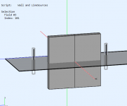
I also found this little example in the ABEC demos folder, a virtual line source with wall in the way, interesting.

I also found this little example in the ABEC demos folder, a virtual line source with wall in the way, interesting.
Attachments
Like you, I don't like those "horns" either. One thing that keeps popping up in my head is the mini line array from member FoLLgoTT, where he made a waveguided array using little drivers that limited the vertical dispersion by using vanes.
I keep thinking, as the frequency shaded array only has about one strong pair of horns left, in the upper frequencies, if short vanes between the drivers would limit the vertical energy, enough to make them that much more "ideal"...
Maybe fun for an ABEC experiment? Seeing the wavelengths involved, the vanes shouldn't have to be all that long to have an effect. I mean even my back-mounting has an effect on the bundling of upper frequencies. Using part of a circle between the drivers may have a sufficient effect to limit the dispersion.
Attachments
I really don't like the "horns" that develop in some of these configurations. The nulls punctuating the polar seem benign enough but the off axis peaks concern me.
I also found this little example in the ABEC demos folder, a virtual line source with wall in the way, interesting.
I really need to learn to use abec...
Like you, I don't like those "horns" either. One thing that keeps popping up in my head is the mini line array from member FoLLgoTT, where he made a waveguided array using little drivers that limited the vertical dispersion by using vanes.
I keep thinking, as the frequency shaded array only has about one strong pair of horns left, in the upper frequencies, if short vanes between the drivers would limit the vertical energy, enough to make them that much more "ideal"...
Maybe fun for an ABEC experiment? Seeing the wavelengths involved, the vanes shouldn't have to be all that long to have an effect. I mean even my back-mounting has an effect on the bundling of upper frequencies. Using part of a circle between the drivers may have a sufficient effect to limit the dispersion.
That was an interesting start to the thread by Follgott but as I recall he ended up with something entirely different.
Joseph Crowe proposed line array with smooth dividers between drivers in one of the line array threads. Speaking of him, he had a nice horn for 2 vertically stacked planar drivers. Speaking of planar drivers, GRS has a very interesting ecoomically priced family of them. One of them is 3.5" square and might subsitute for and provide a good directivity match for a TC9
GRS PT2522-4 3-1/2" Planar Tweeter 4 Ohm
I found its bigger brothers more interesting and have been playing with tekton arrays with them at center
GRS PT6816-8 8" Planar Slim Tweeter 8 Ohm
these OB arrays look pretty good on paper albeit not quite as good as my arrays would be shaded; but they would fit much better in my office
It would be fun and not very obtrusive if a small vane would guide the upper wave results. The rest is covered already with an array like this. Every bit of help to improve upon it is welcome though.
I do remember Joseph's horns on Crumboo's thread.
Adding planar drivers for the top end would still need a crossover, which I'd like to avoid.
The fractal array itself showed a lot of promise but still is hard to successfully implement due to space constraints.
FoLLgoTT has done a lot of experimenting with different designs. Most of them are interesting at the least, I did catch what he ended up with. *** all of you know, I'm simply sticking to what I've got and trying to come up with ways to improve it.
Not being able to go into the garage to finish phase one, the frequency shading, means I've got way too much time to come up with other ideas 😀.
Last edited:
If you have a 3D printer, vanes would be easy enough to try. Sounds like you have a lot of time available for printing them 🙂
I think I'm done with line array with tweeter at center. If I were not convinced I should never say never I would be more definite. Horizontal directivity matching isn't all that difficult; vertical directivity matching leads to other approaches - like fractal and tekton arrays for example.
I think I'm done with line array with tweeter at center. If I were not convinced I should never say never I would be more definite. Horizontal directivity matching isn't all that difficult; vertical directivity matching leads to other approaches - like fractal and tekton arrays for example.
I have acces to a 3D printer at work, but I wouldn't use a filament printer.
I'd rather have it printed on an SLS printer. But first I'd need to test the idea etc..
Maybe I need some ABEC in my life too 🙂.
I'd rather have it printed on an SLS printer. But first I'd need to test the idea etc..
Maybe I need some ABEC in my life too 🙂.
I keep thinking, as the frequency shaded array only has about one strong pair of horns left, in the upper frequencies, if short vanes between the drivers would limit the vertical energy, enough to make them that much more "ideal"...
Maybe fun for an ABEC experiment? Seeing the wavelengths involved, the vanes shouldn't have to be all that long to have an effect. I mean even my back-mounting has an effect on the bundling of upper frequencies. Using part of a circle between the drivers may have a sufficient effect to limit the dispersion.
You are good with CAD which is half the battle with ABEC/AKABAK. If you can make a simple model of the array cabinet, roundover, vanes and cone profile then I can help you simulate it. Quarter symmetry helps a lot with solving time so making it symmetrical is worth while. You have most of it done already, up to you if you want to give it a go. Just don't make the vanes too thin or the mesh will have to be dense to cover it.
The diaphragm can be simulated from a CAD drawing made into a mesh or via the diaphragm tool, as you already have a good model the CAD might be better.
I really need to learn to use abec...
Maybe I need some ABEC in my life too 🙂.
If you guys want to learn I can help you. Have a look at the video I posted in my ABEC thread that I found, he has now posted one on ABEC too.
Akabak might be better to start with as everything can be done through point and click. ABEC needs scripts which are not difficult once you understand what the elements do.
I can post some scripts and explain what the various sections means if you want that, but please remember that explaining something takes a lot more time that doing it 😉
I have a student license for AKABAK which I got in response for my request for a student license of ABEC which seems to be no longer downloadable from the website. I can run ATH through the STL generation step but I've had no luck with AKABAK translation of ATH ABEC scripts. Hopefully, I just need a little help getting started.
First help though is finding that link to a video in your thread, search tool didn't help, nor did a quick scan through the thread. Google search for ABEC turns up Swiss ball bearings used in inline speedskating, which I used to do 🙂
First help though is finding that link to a video in your thread, search tool didn't help, nor did a quick scan through the thread. Google search for ABEC turns up Swiss ball bearings used in inline speedskating, which I used to do 🙂
- Home
- Loudspeakers
- Full Range
- Full range line array for wall or corner placement