Now where did I see that before... 🙂

Pseudo-coaxial with narrow directivity (and Horbach-Keele filters)
or...
https://www.diyaudio.com/forums/multi-way/263353-portal-controlled-dispersion-tripole-4.html#post4097732
Pseudo-coaxial with narrow directivity (and Horbach-Keele filters)
or...
https://www.diyaudio.com/forums/multi-way/263353-portal-controlled-dispersion-tripole-4.html#post4097732
Here are the polar maps. All I did was copy and paste the sandhorn sim from a couple of days ago, pointed to the new waveguide, and repositioned the drivers inward.
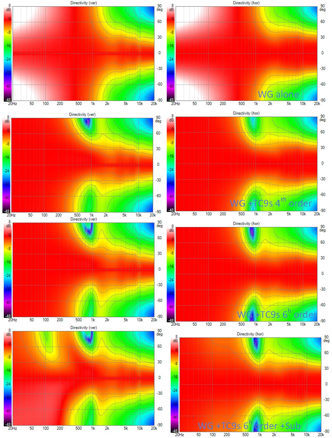
The horizontal directivity is great and this is with a 1050 Hz XO, slightly higher which might be a benefit at high spl if the CD has to reach for 1 khz.
There is clearly some work to be done on the vertical directivity. The sub can be moved up or down somewhat and the overlap between it and the tc9s can be played with but what it really needs is an upper woofer or upper and lower midwoofer arrays replacing the TD15
Attachments

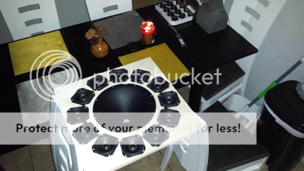
The other place one sees concentric circles of drivers is in the Danley Synergy patent but now we can see they don't have to be within single point summation distance to work well.
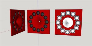
I've been thinking there may be some magic in concentricity instead of rows and columns of drivers around the waveguide. With concentric mounting of the outer drivers, the path length to the LP is the same for all outer drivers. Of course once you go off axis, that changes but maybe it helps a little bit.
I've been thinking there may be some magic in concentricity instead of rows and columns of drivers around the waveguide. With concentric mounting of the outer drivers, the path length to the LP is the same for all outer drivers. Of course once you go off axis, that changes but maybe it helps a little bit.
a good question. here is a quick and dirty answer.
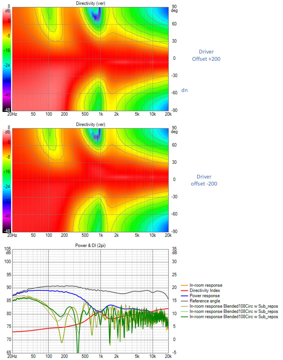
The center of the vertical window moves up or down with the drivers but the inroom response still shows floor reflection nulls, as shown in the overlay traces in the lowest graph.
I think upper and lower woofers playing up through 500 Hz or so are needed to fix this.
The center of the vertical window moves up or down with the drivers but the inroom response still shows floor reflection nulls, as shown in the overlay traces in the lowest graph.
I think upper and lower woofers playing up through 500 Hz or so are needed to fix this.
Attachments

Sorry if I sounded like teacher telling you off, your images are worth looking at so I do click on them but I hate having to keep going back in the browser 🙂
I took your comment as purely helpful, as you continually are to me and others 🙂
Ok, just to see how this works and make sure understand the image wrap thingy...
Gonna do it around the ATTACH
and inside the ATTACH
To see what, if either, work.
Because neither seems to work in Preview mode ???
edit: haha, i clearly don't get it yet...
posting dummy i am...
I optimized the woofer height and the overlap between the tc9s and the woofer. This gave me fairly decent vertical polars.
but when I looked at the EQed room response vs vertical offset I saw it had too much variation with the vertical in the overlap region
OTOH the constancy of the directivity in the waveguide range is amazing
but when I looked at the EQed room response vs vertical offset I saw it had too much variation with the vertical in the overlap region
OTOH the constancy of the directivity in the waveguide range is amazing
Attachments
That's one reason why I want to keep it going as low as I can 🙂 Here is a bigger one for you to try with a 1.4" throat, this one is axisymmetric so you can mirror the horizontal to vertical. Maybe you would like to try some FE120's with this?OTOH the constancy of the directivity in the waveguide range is amazing
One other thing to keep in mind is that these are infinite baffle simulations so they have no baffle diffraction, that would need to be added in Vituix to be more realistic. I can do it in ABEC but then I have to model the exact enclosure which takes a lot longer.
Attachments
Yes, I want the same but I'm trying to do it with drivers outside the waveguide, still having trouble with the floor...
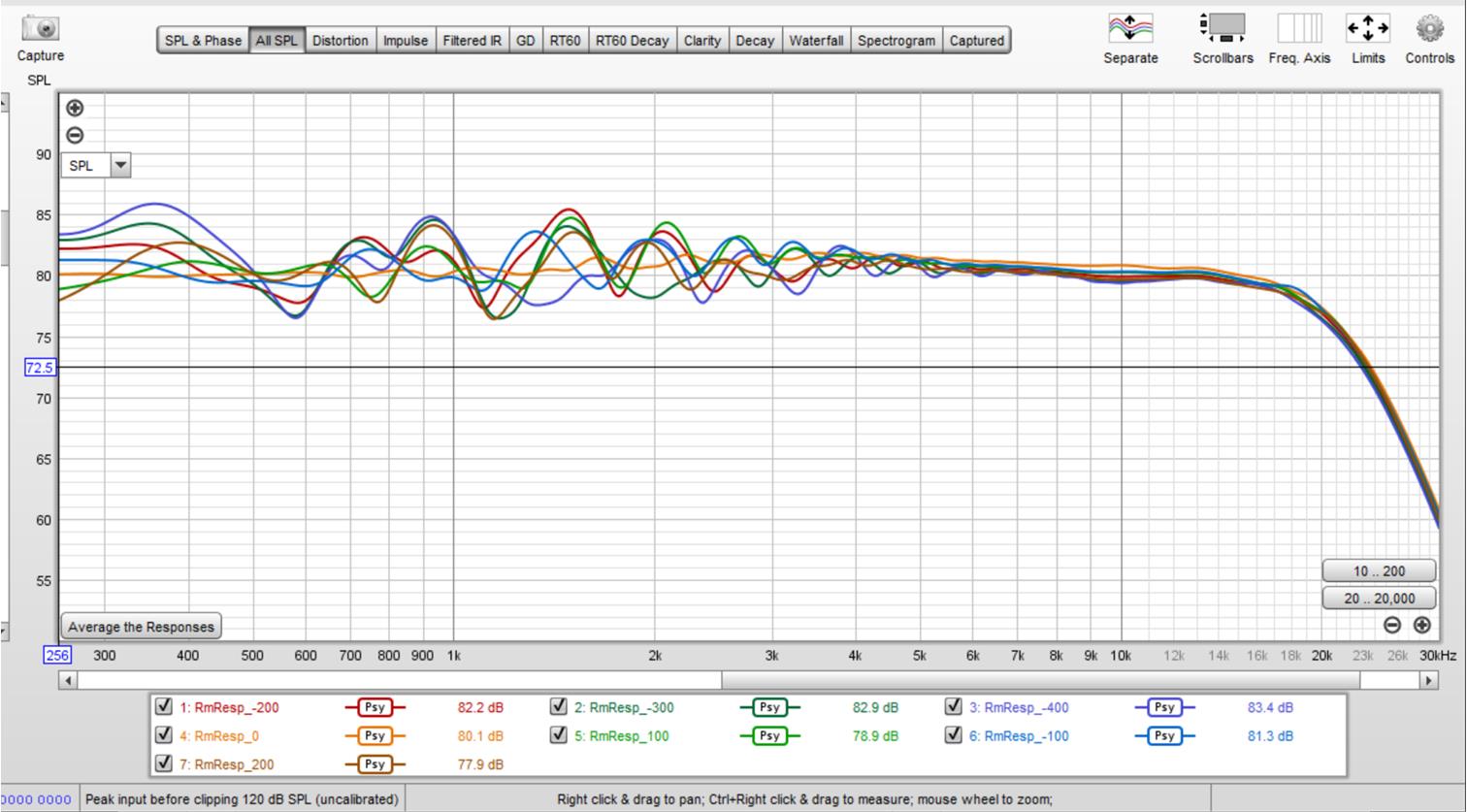
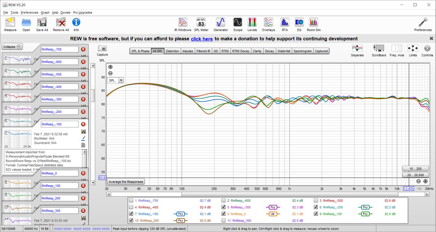
Just a note, If you look at a single TC9, equalized, it will perform as good on that top end as a good horn. It won't have the SPL capability though.

A single TC9, from -200, -100, 0, +100, +200 with floor and ceiling absorption at -20 dB.
But... and it is a big but... For everything below the crossover to the waveguide, I like the results of an array better than what was shown so far.
Way more even/uniform under differing circumstances/heights.
I do think we need the vertical spread of drivers to be able to keep that.
Attachments
I don't know that I agree with that, the directivity of the TC9 is fixed by it's size and shape, it is neither constant or steadily rising, for a single driver it is not at all bad but it does not have the control of a good horn.Just a note, If you look at a single TC9, equalized, it will perform as good on that top end as a good horn. It won't have the SPL capability though.
I agree with this and I suspect that the array can not easily be matched here.But... and it is a big but... For everything below the crossover to the waveguide, I like the results of an array better than what was shown so far.
Yes which is where the problems start 🙂I do think we need the vertical spread of drivers to be able to keep that.
I think you know what I'm getting at 🙂, just look at that top above 7 KHz, that is well within anything we'd want in the vertical direction. I'm only talking about that top end, as mentioned, in the vertical plots shown.
All I'm saying is that the total picture of the horn + adjacent drivers so far isn't very convincing right now. The directivity isn't even in any direction, it swells and narrows and isn't well controlled.
If a synergy could be made that keeps the good output of a horn, it could form the middle part of an array for the bottom end. If we can stay within that quarter wavelength to hand off the horn to the array, it will act as one.
Which is the reason I brought up the single driver. As we're trying to create a single ideal source in a way, but one that can be just that within a room featuring a floor and ceiling.
Last edited:
The TC9 is going to beam more than the waveguide.
The waveguide needs help in the vertical dimension and thus the circle of TC9s. That wasn't enough help. The next step is to expand the array, replacing the 15" woofer at floor level with pairs of 8" woofers above and below the TC9. These have to be as close as possible to the TC9s to give a good cross to them circa 500 Hz; perhaps 6.5" drivers would have been better. With those added drivers close to the tc9s, the result loses vertical control around 250 Hz and so we will see the room having too much influence there. Putting additional drivers at floor level helps marginally but what is really needed is another complementary pair at top and bottom. So we are back with something as tall as or almost as tall as a line array which stands to reason if you want the same vertical control.
simulation results in next post
Figure out what you'd want ideally, everything above 7 KHz to be perfect or everything between ~100 up to 7 KHz to be perfect.
Don't get hung up on what I'm saying, just meant to make another point entirely. 😉
We're deviating from an array, with a horn top to get better results. However everything from that array still is superior in the frequency band that would count the most for me.
No, I don't think the TC9 (or actually, a 3.5" driver size) is the ideal source. But what I'm getting at is that we shouldn't settle for anything less than what it already does well. Which means that a transition of a horn to the lower frequencies should be at least as seamless as a single idealized source.
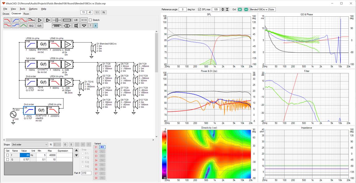
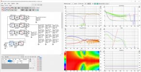
This will show you what I simulated and polar maps.

The equalization isn't perfect but the polar maps are normalized so its sufficient for our purposes.
Here are the room responses with vertical offsets, first around the seated ear height and then over the full range of seated through standing
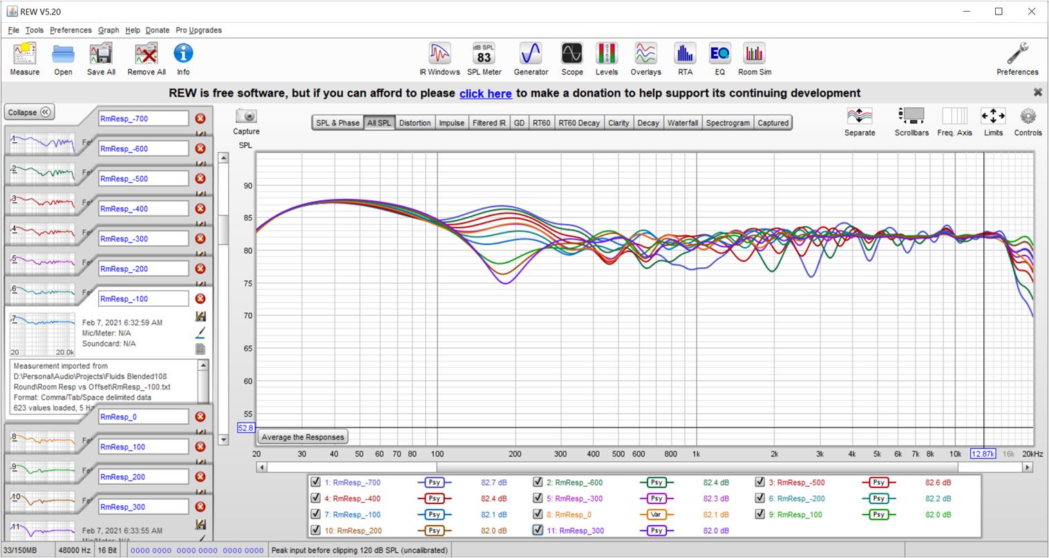
BTW, these room responses were taken with the speaker in a corner, with wall, floor and ceiling reflections enabled and only 2 db of absorption.
I think the 1 kHz ++ range is compelling. Below 1 kHz the room has too much influence; the loss of vertical control around 250 Hz stands out. Fluid has provided me with data on larger waveguide which will definitely help in the 500 Hz to 1000 Hz range. Improving around 200 Hz means making the ensemble taller but that is under the Shroeder limit and the room is going to have its way regardless.
The larger waveguide has a 1.4" exit so its top end might not be as good as a 1" driver.
The equalization isn't perfect but the polar maps are normalized so its sufficient for our purposes.
Here are the room responses with vertical offsets, first around the seated ear height and then over the full range of seated through standing
BTW, these room responses were taken with the speaker in a corner, with wall, floor and ceiling reflections enabled and only 2 db of absorption.
I think the 1 kHz ++ range is compelling. Below 1 kHz the room has too much influence; the loss of vertical control around 250 Hz stands out. Fluid has provided me with data on larger waveguide which will definitely help in the 500 Hz to 1000 Hz range. Improving around 200 Hz means making the ensemble taller but that is under the Shroeder limit and the room is going to have its way regardless.
The larger waveguide has a 1.4" exit so its top end might not be as good as a 1" driver.
Attachments
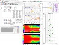
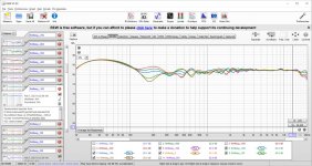

Figure out what you'd want ideally, everything above 7 KHz to be perfect or everything between ~100 up to 7 KHz to be perfect.
My interest is to find how good a system can be made with this particular style/architecture of speaker; don't imagine I want to build one. I'm not there yet, but I am tempted.
I haven't changed my opinion that the line array is best for small footprint and that Synergy is as good or maybe even better if the waveguide is large enough.
All this is leading towards an expanding array with Synergy at center and the question for me is how big that center Synergy waveguide needs to be to avoid compromises or excessive room influence in the low midrange. Some form of that question has been around for some time. At least now the solutions we are coming up with are starting to look fairly good.
I see a synergy as a practical MTM, in that we can get the drivers close enough to act as one, but on the other end an array is excellent at avoiding/using floor/ceiling bounce (*). A fusion of some sort seems to have ideal properties.
(*)= Almost similar to the multisub solution in a way.
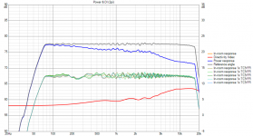
If the drivers don't act as one over their bandwidth of interest, the side bands are starting to appear. (as can be seen in the full range lines). That's the puzzle I'm seeing here... 🙂
Meanwhile I'll be looking at ways to improve the full range array, as I do believe we could soften the side bands with some help in directivity pattern control (**).
(**)= long term goals really, taking baby steps toward that goal. 😀
I've been looking at the directivity patterns we used for the TC9 in these sims, I believe the real world results are a bit better than what is used in these sims (at least out to 30 degree). Which will have both advantages and draw-backs.
If we can limit vertical dispersion and keep horizontal the same, the side bands will soften. Even back mounting, like I've used, already has an effect on the directivity patterns. Which means if we could shape this output at will, to come closer to something that works well in such an array, another step up in performance is waiting there. If there aren't some real compromises that can undermine this line of thought.
(*)= Almost similar to the multisub solution in a way.
If the drivers don't act as one over their bandwidth of interest, the side bands are starting to appear. (as can be seen in the full range lines). That's the puzzle I'm seeing here... 🙂
Meanwhile I'll be looking at ways to improve the full range array, as I do believe we could soften the side bands with some help in directivity pattern control (**).
(**)= long term goals really, taking baby steps toward that goal. 😀
I've been looking at the directivity patterns we used for the TC9 in these sims, I believe the real world results are a bit better than what is used in these sims (at least out to 30 degree). Which will have both advantages and draw-backs.
If we can limit vertical dispersion and keep horizontal the same, the side bands will soften. Even back mounting, like I've used, already has an effect on the directivity patterns. Which means if we could shape this output at will, to come closer to something that works well in such an array, another step up in performance is waiting there. If there aren't some real compromises that can undermine this line of thought.
Last edited:
- Home
- Loudspeakers
- Full Range
- Full range line array for wall or corner placement