Hi Ron, thanks for nice reply...wasn't blunt of offensive at all...quite helpful ")
And please don't take my early (perhaps too early to state) subjective comparisons as any kind of negativity towards line-arrays.
As I've said all along, this project is primarily about learning....more so than trying to achieve any kind of in-room response.
Now I realize most might say 'how can a person make good subjective comparisons without achieving good in-room response?', but honestly i think I can.
I've spent alot of time learning to separate speaker problems from room problems. And I've set up alot of different systems in a lot of different rooms, venues, and outdoor locations.
Doesn't make me an expert by any means...I'm finding out how little i know every day...and enjoying doing so
Speaking of knowing only a little...yes, you are right about the 1/4 WL spacing not applying to line-arrays.
Why do I keep forgetting 1/2 WL is the commonly accepted measure for HF line break apart (loss of vertical directivity and lobing).....
Do you agree with that rule of thumb?
That would push tightly packed TC9 line breakup up to about 2300 Hz ....where it sounds like theory says combing has to begin.
I see prosound line boxes are going to ever tighter spacing via smaller drivers and inventive acoustical plumbing to maintain HF line directivity and avoid lobing.
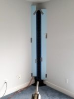
Anyway, with regards to the floor to ceiling corner array, I have been doing most testing in a normal 8 ft ceiling room with smoother side walls and less furniture etc.....as pictured below. Sorry if the big room pict led you to believe all my impressions have been coming from that placement alone.
I'm really not all that concerned with side wall reflections right now, as I know that's just a different form of "floor bounce" so to speak, and is something I know how to filter out of measurements.
That said, I'm not a fan of FDW for such filtering (throws away too much info imo). I prefer averaging multiple measurements, or better, a moving mic that can track group delay as mic moves. Smaart is a very capable measuring tool if you're unfamiliar with it.)
A quick moving mic measurement is below, as well as one of a close miced single 4 driver section.
What I'm really interested in, is seeing how well the 'infinite line theory holds up 'floor-to-ceiling in a corner.'...particularly how high up in freq the theory appears to work.
Stepping back to the big picture game plan..... as always, my goal is to first separate speaker from room, then separate those two from how the line-itself interacts with room.
It hit me that the TC9s are the first speaker I've ever worked on when FIR might not be needed ! I mean, without a crossover, EQ's should all be minimum phase. The only advantage I can see that FIR offers is embedding alot of IIRs easily, and perhaps low end phase work if you believe that helps or want to add a sub.
And I'm still of the opinion EQ is never a solution to the room (unless you're happy to a spot, which I'm simply not. I still have full range electrostats I'd be listening to if I were).
Acoustic issues, reflections, decay times, etc...need acoustic solutions imo, not EQ's and delays. Knocking down low end modes are about the only valid room EQ i think.
OK, so I plan to do a moderate amount of IIR smoothing based on something between moving mic averaging at distance and single section close response, TBD. Then I'll knock down side wall reflections with whatever wing material proves best for corner placement. Then I plan to see how the room responds to the line, in the corner and free standing. I should says rooms plural..and outdoors. And yes, I still intend to measure from distant rooms...never know what we can learn just trying stuff Then...sigh...maybe I'll finally get to shading and delay...and checking out the cbt ...lots mo' learning ahead!
And please don't take my early (perhaps too early to state) subjective comparisons as any kind of negativity towards line-arrays.
As I've said all along, this project is primarily about learning....more so than trying to achieve any kind of in-room response.
Now I realize most might say 'how can a person make good subjective comparisons without achieving good in-room response?', but honestly i think I can.
I've spent alot of time learning to separate speaker problems from room problems. And I've set up alot of different systems in a lot of different rooms, venues, and outdoor locations.
Doesn't make me an expert by any means...I'm finding out how little i know every day...and enjoying doing so
Speaking of knowing only a little...yes, you are right about the 1/4 WL spacing not applying to line-arrays.
Why do I keep forgetting 1/2 WL is the commonly accepted measure for HF line break apart (loss of vertical directivity and lobing).....
Do you agree with that rule of thumb?
That would push tightly packed TC9 line breakup up to about 2300 Hz ....where it sounds like theory says combing has to begin.
I see prosound line boxes are going to ever tighter spacing via smaller drivers and inventive acoustical plumbing to maintain HF line directivity and avoid lobing.
Anyway, with regards to the floor to ceiling corner array, I have been doing most testing in a normal 8 ft ceiling room with smoother side walls and less furniture etc.....as pictured below. Sorry if the big room pict led you to believe all my impressions have been coming from that placement alone.
I'm really not all that concerned with side wall reflections right now, as I know that's just a different form of "floor bounce" so to speak, and is something I know how to filter out of measurements.
That said, I'm not a fan of FDW for such filtering (throws away too much info imo). I prefer averaging multiple measurements, or better, a moving mic that can track group delay as mic moves. Smaart is a very capable measuring tool if you're unfamiliar with it.)
A quick moving mic measurement is below, as well as one of a close miced single 4 driver section.
What I'm really interested in, is seeing how well the 'infinite line theory holds up 'floor-to-ceiling in a corner.'...particularly how high up in freq the theory appears to work.
Stepping back to the big picture game plan..... as always, my goal is to first separate speaker from room, then separate those two from how the line-itself interacts with room.
It hit me that the TC9s are the first speaker I've ever worked on when FIR might not be needed ! I mean, without a crossover, EQ's should all be minimum phase. The only advantage I can see that FIR offers is embedding alot of IIRs easily, and perhaps low end phase work if you believe that helps or want to add a sub.
And I'm still of the opinion EQ is never a solution to the room (unless you're happy to a spot, which I'm simply not. I still have full range electrostats I'd be listening to if I were).
Acoustic issues, reflections, decay times, etc...need acoustic solutions imo, not EQ's and delays. Knocking down low end modes are about the only valid room EQ i think.
OK, so I plan to do a moderate amount of IIR smoothing based on something between moving mic averaging at distance and single section close response, TBD. Then I'll knock down side wall reflections with whatever wing material proves best for corner placement. Then I plan to see how the room responds to the line, in the corner and free standing. I should says rooms plural..and outdoors. And yes, I still intend to measure from distant rooms...never know what we can learn just trying stuff
Then...sigh...maybe I'll finally get to shading and delay...and checking out the cbt ...lots mo' learning ahead!Attachments
Sorry Mark, I can't agree with all of those points you made.
I don't know which frequency dependent windows you have used so far, there is a big difference between the implementation of it in REW compared to the one used in DRC itself to do it's processing with.
Any work done with EQ with longer windows or even waving the mic is "letting in" part of the room itself without any regard for 'timing' of that first wave front. A lot of measurement points averaged could get you closer to the true speaker IR though and keep actual phase data.
But if you let back in the reflections in the actual listening session(s), it will still have it's way with the outcome and color its sound in many ways. These aren't horns that avoid the room. May it be for good or for bad.
All phase wraps in ra7's measurement point back to something happening in the room, if you gate it before reflections happen, they will disappear. Or if you look at it with a frequency dependent window, it will disappear as well.
Looking at that picture with the much cleaner wall you showed, I still see the transition from that temporary wave guide to that wall. It's like a horn that changes shape midway. Like it or not, it will also determine the outcome. The more gradual it will flow, the less detrimental it will be. Right now it is at the same distance for all drivers, so it does not get filtered out by the array itself.
To get a mental picture of that "avering out by the array" I keep talking about... picture yourself doing multiple measurements of a speaker indoors. The more measurement points you use, the less unique reflections show up in the average of those measurements. Well, an array of drivers works the other way around. Each driver will have a unique set of reflections as seen from a listeners perspective. But our ear gets to hear the average of all those drivers, so each unique reflection from each single driver gets filtered out, or "averaged". What remains is what they have in common. The parallel planes is an example of that.
An array as measured outside still resembles a finite array. It needs to have at least the floor and ceiling to be able to "mimic" or come close to an infinite array. So that's why I keep hammering on the limited use of taking the outside measurements as a reference. You don't "see" the array as it was ment when it's outside, at least not how I like to see my favorite kind of array.
The frequency dependent window is to separate the frequency data of the first wave front that 'hits your ear' from the rest of the room response. My specific window is as short as I can get away with in the mid frequencies and longer up top to account for the delayed arrival of high frequencies (from the upper and lower drivers). That specific view gets "corrected back" to an ideal (well almost) IR by DRC. The window is no longer than needed to 'look' at what the speaker has done, from a listeners perspective.
Have you ever filtered out a single frequency to look at in one of your measurements? You'll see what the wave shape is and that what follows it where it goes back to silence. How long is that first wave at high frequencies? How long is it at low frequencies? What happens afterwards? It is a start/stop relationship the speaker has with the incoming signal. I'm only trying to help it start, but can't or won't help it stop, as that's a possible mix of speaker driver imbalance and/or in room effects. DRC tries to alter the signal rising signal for me so it's outcome is a pure Dirac pulse again.
Helping it start edits that first wave front, where phase is not altered by all it encounters within the room. Anything longer than that short window includes all other variables into the mix.
There is simply no way to get good sound out of an array like this floor to ceiling (full range) type without EQ-ing the entire frequency range you want to get out of it. You shape it to your preferred in room curve (which isn't a flat line for me).
The array by itself provides you with a few interesting features. 10 dB of correction on the array is like ~0.4 dB correction on a single driver.
The power it can handle without breaking is about 240 watt. So don't be too scared, as at a driver level it will be peanuts. This doesn't mean I advocate big bumps or dips as correction, it just shows the general curve may deviate pretty far from flat without getting into trouble, the distortion graphs will probably tell you if you move too far.
I do not agree with a half wave rule either for an array, the spacing plus distance to the array determines where combing starts.
Try and correct an array to flat, at a single spot, with an early waterfall graph as your guide line until it looks somewhat like this (at listening distance):

If you have a waterfall like that (ain't going to happen without support from the room *) then open the correction by itself, doesn't matter if it is consists out of IIR EQ tweaks or is FIR based. The example here is FIR (minimum phase above 500 Hz) with (P)EQ applied afterwards.
If you open that correction curve by itself you'll start to see where combing becomes an issue (at that distance). You'll start to see excessive peaks (compared to the other correction tweaks) in the correction curve that points you to the combing dips. That's when it will become clear to you there actually is combing happening and at what frequency it starts.
And it will move, if the listening distance changes!
I actually dial down the excessive correction of the places where I find the combing dips. Which at my listening distance starts at about ~ 7 KHz and consists of a very narrow dip if compensated for, not quite deep yet.
That dip will actually move up or down in frequency if you move to a different listening distance. Next one for me is at 10 KHz and another at 11.5 KHz, again at my specific listening distance.
It would move up to a higher frequency if the listening distance is increased.
However, aside from the combing dips, the rest of the FR curve will still hold and follow the same general trends you aim for.
Even though I can find the combing this way in my measurements, the same does not apply to my ears. Though this may be heard out in the room if you keep the excessive correction for those dips in place.
By the way, I don't recommend the waterfall method as described above as a general way of getting things done. Certainly not if reflections are present. I still use varying time-length settings within such a waterfall to adjust for a specific frequency, just as a frequency dependent window would do.
The FDW correction makes all other measurements that follow with correction in place (including a moving mic measurement) look beautiful, if the room supports it (again). Without help from the room you'll get the same bumpy ride as any other speaker would give you that has no other means to avoid the room. However, an array will help average out a lot of the in room stuff that is present in a non dedicated room, except for the parallel planes to that array.
(*)= There isn't much difference for me if I just pick one single sweet spot measurement to base my correction on, or if I use an average of several measurements. That's because of one reason only, the suppressed in room first reflections, done the old fashioned way. 3 Big absorbing panels in critical places.

Those panels hammer down the first reflections out in the room. Not exactly studio like yet, but not quite an average home or in-room result either.
To me, that is the power of the array, not many other speaker types could have done or achieved that with so little help as seen from the listening spot.
If you have lots of experience with sound within rooms you should know the influence these reflections can have on what we hear. Most detrimental being the ones that happen within 6 ms, at least to imaging and tonality. Tonal balance gets sorted out over an even longer window, something the moving mic measurement is quite good at to create a good balance.
The above is my opinion only, based on a lot of time invested to get me where I wanted to be. Not nearly done with it either. I wanted this reflection "free" (or rather suppressed) zone from the start to maximize imaging and get a smooth tonal balance across the room. And succeeded with that. The in room balance I use is my preference. It does seem to have worked for others that have heard it.
By the way, I've done the IIR correction by hand, I never got it as clean and nice as starting with DRC (largely acting in minimum phase mode). I've also done my share of mic waving, but that's just accounting for overall room response. I've never been pleased with that long term.
As without removing the reflections, an in room response will always vary from spot to spot. Unless the speaker helps you with avoiding it.
I do introduce a "virtual room" as late reflections as it is a nice way to add a little live feel without upsetting tonal balance or imaging. Based on reading a lot of theory from David Griesinger after first being clued to it's possible outcome by DIY member werewolf, years ago on a different forum. The same fellow that wrote the thread about Infinite Line Source theory.
My latest experiments, another re-run of earlier experiments, with cross talk cancellation shows me there's lots more to be had from stereo by really looking what each ear gets to process. Basically it does explain a lot about differences heard, even from speakers that seem to have very similar FR.
Hope you get something out of this. Even changing just one variable within DRC, with the exact same FR target has shown me such differences in what I've heard, this is why I keep pushing towards that, as it's easy enough to try.
I don't know which frequency dependent windows you have used so far, there is a big difference between the implementation of it in REW compared to the one used in DRC itself to do it's processing with.
Any work done with EQ with longer windows or even waving the mic is "letting in" part of the room itself without any regard for 'timing' of that first wave front. A lot of measurement points averaged could get you closer to the true speaker IR though and keep actual phase data.
But if you let back in the reflections in the actual listening session(s), it will still have it's way with the outcome and color its sound in many ways. These aren't horns that avoid the room. May it be for good or for bad.
All phase wraps in ra7's measurement point back to something happening in the room, if you gate it before reflections happen, they will disappear. Or if you look at it with a frequency dependent window, it will disappear as well.
Looking at that picture with the much cleaner wall you showed, I still see the transition from that temporary wave guide to that wall. It's like a horn that changes shape midway. Like it or not, it will also determine the outcome. The more gradual it will flow, the less detrimental it will be. Right now it is at the same distance for all drivers, so it does not get filtered out by the array itself.
To get a mental picture of that "avering out by the array" I keep talking about... picture yourself doing multiple measurements of a speaker indoors. The more measurement points you use, the less unique reflections show up in the average of those measurements. Well, an array of drivers works the other way around. Each driver will have a unique set of reflections as seen from a listeners perspective. But our ear gets to hear the average of all those drivers, so each unique reflection from each single driver gets filtered out, or "averaged". What remains is what they have in common. The parallel planes is an example of that.
An array as measured outside still resembles a finite array. It needs to have at least the floor and ceiling to be able to "mimic" or come close to an infinite array. So that's why I keep hammering on the limited use of taking the outside measurements as a reference. You don't "see" the array as it was ment when it's outside, at least not how I like to see my favorite kind of array.
The frequency dependent window is to separate the frequency data of the first wave front that 'hits your ear' from the rest of the room response. My specific window is as short as I can get away with in the mid frequencies and longer up top to account for the delayed arrival of high frequencies (from the upper and lower drivers). That specific view gets "corrected back" to an ideal (well almost) IR by DRC. The window is no longer than needed to 'look' at what the speaker has done, from a listeners perspective.
Have you ever filtered out a single frequency to look at in one of your measurements? You'll see what the wave shape is and that what follows it where it goes back to silence. How long is that first wave at high frequencies? How long is it at low frequencies? What happens afterwards? It is a start/stop relationship the speaker has with the incoming signal. I'm only trying to help it start, but can't or won't help it stop, as that's a possible mix of speaker driver imbalance and/or in room effects. DRC tries to alter the signal rising signal for me so it's outcome is a pure Dirac pulse again.
Helping it start edits that first wave front, where phase is not altered by all it encounters within the room. Anything longer than that short window includes all other variables into the mix.
There is simply no way to get good sound out of an array like this floor to ceiling (full range) type without EQ-ing the entire frequency range you want to get out of it. You shape it to your preferred in room curve (which isn't a flat line for me).
The array by itself provides you with a few interesting features. 10 dB of correction on the array is like ~0.4 dB correction on a single driver.
The power it can handle without breaking is about 240 watt. So don't be too scared, as at a driver level it will be peanuts. This doesn't mean I advocate big bumps or dips as correction, it just shows the general curve may deviate pretty far from flat without getting into trouble, the distortion graphs will probably tell you if you move too far.
I do not agree with a half wave rule either for an array, the spacing plus distance to the array determines where combing starts.
Try and correct an array to flat, at a single spot, with an early waterfall graph as your guide line until it looks somewhat like this (at listening distance):
If you have a waterfall like that (ain't going to happen without support from the room *) then open the correction by itself, doesn't matter if it is consists out of IIR EQ tweaks or is FIR based. The example here is FIR (minimum phase above 500 Hz) with (P)EQ applied afterwards.
If you open that correction curve by itself you'll start to see where combing becomes an issue (at that distance). You'll start to see excessive peaks (compared to the other correction tweaks) in the correction curve that points you to the combing dips. That's when it will become clear to you there actually is combing happening and at what frequency it starts.
And it will move, if the listening distance changes!
I actually dial down the excessive correction of the places where I find the combing dips. Which at my listening distance starts at about ~ 7 KHz and consists of a very narrow dip if compensated for, not quite deep yet.
That dip will actually move up or down in frequency if you move to a different listening distance. Next one for me is at 10 KHz and another at 11.5 KHz, again at my specific listening distance.
It would move up to a higher frequency if the listening distance is increased.
However, aside from the combing dips, the rest of the FR curve will still hold and follow the same general trends you aim for.
Even though I can find the combing this way in my measurements, the same does not apply to my ears. Though this may be heard out in the room if you keep the excessive correction for those dips in place.
By the way, I don't recommend the waterfall method as described above as a general way of getting things done. Certainly not if reflections are present. I still use varying time-length settings within such a waterfall to adjust for a specific frequency, just as a frequency dependent window would do.
The FDW correction makes all other measurements that follow with correction in place (including a moving mic measurement) look beautiful, if the room supports it (again
). Without help from the room you'll get the same bumpy ride as any other speaker would give you that has no other means to avoid the room. However, an array will help average out a lot of the in room stuff that is present in a non dedicated room, except for the parallel planes to that array.(*)= There isn't much difference for me if I just pick one single sweet spot measurement to base my correction on, or if I use an average of several measurements. That's because of one reason only, the suppressed in room first reflections, done the old fashioned way. 3 Big absorbing panels in critical places.
Those panels hammer down the first reflections out in the room. Not exactly studio like yet, but not quite an average home or in-room result either.
To me, that is the power of the array, not many other speaker types could have done or achieved that with so little help as seen from the listening spot.
If you have lots of experience with sound within rooms you should know the influence these reflections can have on what we hear. Most detrimental being the ones that happen within 6 ms, at least to imaging and tonality. Tonal balance gets sorted out over an even longer window, something the moving mic measurement is quite good at to create a good balance.
The above is my opinion only, based on a lot of time invested to get me where I wanted to be. Not nearly done with it either. I wanted this reflection "free" (or rather suppressed) zone from the start to maximize imaging and get a smooth tonal balance across the room. And succeeded with that. The in room balance I use is my preference. It does seem to have worked for others that have heard it.
By the way, I've done the IIR correction by hand, I never got it as clean and nice as starting with DRC (largely acting in minimum phase mode). I've also done my share of mic waving, but that's just accounting for overall room response. I've never been pleased with that long term.
As without removing the reflections, an in room response will always vary from spot to spot. Unless the speaker helps you with avoiding it.
I do introduce a "virtual room" as late reflections as it is a nice way to add a little live feel without upsetting tonal balance or imaging. Based on reading a lot of theory from David Griesinger after first being clued to it's possible outcome by DIY member werewolf, years ago on a different forum. The same fellow that wrote the thread about Infinite Line Source theory.
My latest experiments, another re-run of earlier experiments, with cross talk cancellation shows me there's lots more to be had from stereo by really looking what each ear gets to process. Basically it does explain a lot about differences heard, even from speakers that seem to have very similar FR.
Hope you get something out of this. Even changing just one variable within DRC, with the exact same FR target has shown me such differences in what I've heard, this is why I keep pushing towards that, as it's easy enough to try.
Last edited:
All of the EQ tweaks you do form a curve. That curve can be saved or retrieved as well.
So you see how it deviates from a straight line. Where the (P)EQ bumps and dips are etc.
It can be opened as a measurement.
With a FIR filter, it's as simple as opening the wave file (as long as your measurement suite can read it's format). If it's a series of EQ tweaks in a program, just feed it a pure Dirac pulse and record it's outcome to disk. Voila, you get to "see" the tweaks.
Last edited:
Thanks again Ron, your post was obviously trying to be as helpful as possible.
I've been using the freq dependent windowing in REW, until I began doing all my measurements with Smaart. I haven't used REW for quite a while, other than harmonic distortion testing and CEA2010 subwoofer testing.
Smaart also has FDW, but i seldom use it.
Anyway, I fired up REW this morning, and wow...there is no way I can get any kind of sensible phase trace in the room I lasted last posted from, without applying both estimated IR shift and FDW. Using either estimated IR shift or FDW alone, leaves a hopeless multitude of wraps.
Are you able to get any kind of decent raw measurements of phase indoors using REW without FDW? Just using est IR shift?
(When I quit using REW, one of my acid tests on how well tuning came out, was when traces without any FDW looked nearly as good as with (say FDW5).)
I've never seen phase traces that show so much co-mingled interaction...
And most of it appears to be as you said about ra7's traces, room interaction.
I moved the straight column out on the deck, and estimated IR shift by itself removes all but a handful of wraps above 8kHz.
Smaart on the other hand, does a good job of removing wraps, even indoors, without using its FDW capability. The last traces I posted were such. No clue why...
I understand the purpose of FDW is to eliminate reflections as much as possible, and used to play with it and gating a fair amount..
But really, I don't use those much ...I just go outdoors...sorry, couldn't resist
With either program, indoors or out, FDW or not, it's looking pretty clear that response, both mag and phase, get quite squirelly above about 8kHz, .
Which brings me back to the 1/2 WL rule of thumb for HF line propagation...
My understanding is that once that criteria is exceeded, line theory no longer holds for HF, and then yes as you say, spacing plus distance to the array determines when combing starts. But the point in my mind is that once spacing plus distance set the equation, you've lost the benefit of the line. IOW, there is no combing below that 1/2WL freq.
Is my understanding incorrect? Because I sense I must either be incorrect or I don't see how you can disagree with the 1/2WL rule of thumb ...given how widely it seems to be accepted.
I get that the corner floor to ceiling is supposed to replicate an infinite line, but my further understanding is that length of line has nothing to do with HF combining, that length of line is about LF pattern control. Rule of thumb there seems to be a line needs to be about 3x the length of LF wavelength.
I'm hoping to observe some of that LF control, with the array in the corner.
But it's beginning to look pretty clear, once above somewhere between 5 and 8kHz, things may stay a bit messy. Hope not, hope just need to learn more
Oh, the moving mic technique...Smaart is really cool here. Since it is dual channel FFT, it is able to continually track mic movement and stay phase consistent thoughout movement. It adjusts tracking distance at 24 times per second. So that capability, along with its nice suite of averaging parameters, allows for very easy spatial averaging that I've found closely replicates care static measurements averaged together.
I applaud you for you acoustical treatments. That's sooo the way to do things right, imo/ime.
I'm going to try to tune to a single spot now, as you suggest.
Let me first address the 1/2 wavelength spacing. One document I've read that mentions that particular rule is Jim's nflawp. I was well aware of that document during my pré research. In the part about practicality of that same document this rule gets bend some, a bit further in that same document wee see it being relaxed to one wave length spacing. However that half wave length rule did come with valid reasoning.
In this post: https://www.diyaudio.com/forums/full-range/313352-line-array-modified-cbt24.html#post5210070 even Jim sees fit to relax those rules somewhat, even if it is born out of a compromise.
As said, distance from array is another important part in this behavior, so while there certainly is a theoretical base for it, practicality sometimes asks for other solutions.
I decided to look further for possible answers and found some in the research from David Smith, he posted those papers here: https://www.diyaudio.com/forums/multi-way/165596-constant-beam-width-transducers-line-arrays-6.html#post2257395
That paper, and I did some further research into the practicality of the Genesis speakers (where high frequency actually comes from the small round tweeters, and not that continuous line you see)

Next up, the papers from Don Keele, with the simulations of closely spaced sources was also in consideration.
Basically, I dropped the goal to achieve that half wave or even full wave spacing in order to be able to get me a speaker that could have a shot of doing all of the frequencies needed without any crossover at all. That was the primary goal for me, knowing that if there was enough distance from the array, I most probably could get away with it. However I did continue to look at all the lines that passed on this forum measured to try and find a better clue of the how's and why's. I'm also here, aren't I.
You have to think about the theoretical model some more. It assumes perfect sources that work together to be able to sim it.
How do full range drivers really work? At low frequencies they act as a piston source (for all practical purposes). However as you go up in frequency their behavior changes to be able to play those high notes. Mostly acting like a controlled break up state or if you want, more ideally it could be seen as DML like behavior. Fact is, there isn't true perfection here, but most likely there is also a bigger part of that driver that is responsible for the high frequency capabilities than most would assume.
I bet the spacing of those Genesis tweeters isn't much different from the TC9 spacing most of us get.
The TC9 was my choice of poison, because it was a clean driver (neat IR and waterfal plots) that could fill my wish of full range bottom to top without crossovers. Nc535's (and Jim Griffin, among others) choice for the smaller SBA65 could very well be a step up, if one is willing to let go of the bottom part. I wouldn't know yet, I've had one in my hand, boy they are tiny.
I've admitted it before, I was ready with back-up plans should this array not do what I expected from it. But I was also willing to compromise (hopefully just a little) on the bottom and top end, if it were indeed possible to have a crossover-less speaker from bottom to top with a magical midrange.
I do believe that a bit of clever processing, like one finds in DRC can get you closer to quite good top end (and bottom end ) behavior, rather than trying to achieve the same with IIR PEQ done by hand.
First time I used DRC I said: DRC_FIR shrunk my speakers! Before using it I had a wild ride of sound experiences with how I've read how line arrays can act. The big sound people speak of and kinda exiting at times, but with very unpredictable results from one song to the next. Placing those damping panels also had subjective side effects. The thrilling part that I liked was gone with the big orchestra's, one that made me feel like being part of the experience. Most notably removing the ~7 ms reflection from the wall behind the listening seat. It improved imaging (a great deal) but removed a lot of energy in the process.
The virtual "room late reflections" I used later on gave me back that thrill in a controllable way.
I have not used Smaart in a long long time. Basically I started using REW from the start of my array project and stuck with it. Learning the program but also it's limitations and quirks (sorry John, I've seen it evolve).
There was no frequency dependent window in REW when I started my DSP adventure. So I had to go trough IR, waterfall, spectogram and Frequency response to find the answers I needed at the time. This taught me a lot of how it all interacts, these different views of the same data. (spend many hours learning and figuring out where to look to explain what I had)
All you see with these phase wraps and arrays is a form of interaction. The most important part though is when those wraps start. Not the fact that they are there. The more you avoid those reflections, the less wraps you'll see. I have them, those wraps, but can get rid of them in my processed top end if I gate before the first clear reflection (that I didn't quite get rid of, due to restrictions set out by my sweetheart) at just over 7 ms.
Meaning I have ~7 ms of reasonably clean top end phase behavior (at the listening spot).
Unsmoothed:

Graph posted earlier on an APL_TDA thread...
Now go back and look at how long those high frequencies really last. By the time 6 ms have passed, we already got a clear picture of that top end, as needed for placement and imaging. Tonal balance might still be a "work in process" in our head though. As that perceived balance also determines how something sounds. Which is why you couldn't EQ out a room if you wanted, as our head simply analyzes what parts that neat frequency curve exists of. Arrival timing being a definitive part of that analyzing.
Don't fear the wraps, but keep an eye on why they are there and especially when they form. I can set quite a long FDW when in cycles mode while still keeping the phase plot as expected. Meaning my ears get a pretty clear shot at that first wave front, before the room starts to mess it all up. That's something also seen in the other plots I've shown before like the APL_TDA plot or the later REW wavelet variant.
You do remember these are floor to ceiling speakers right? Not a single driver as measured outside, away from boundaries. How on earth could it avoid the room while also reaching your ears. So forget about those wraps for a moment. Set up or prepare the speakers to get the least reflections in your IR till about 6-7 ms or more (goal for me was to get them at least less than 10% of the main pulse). That way it did not cause abrupt phase changes anymore. The first 3 ms clean up being critical!, up to 6 ms advisable to improve imaging, up to 20 ms for nutcases like me.
It gets both easier and harder though, once the early ones are removed.
If you can't get that first 6 ms clean (don't look at the "series" or "train of arrivals" under that ~0.5-0.6 ms mark as that is part of the spread out arrival of the separate drivers in the array. Restoring that, for example with DRC (much easier than trying to do something similar by hand) will even out and clean up that part of the IR. If you have reflections below say the 6 ms mark that stand out, use an average of a few measurements around the sweet spot.
If that average turns out cleaner, you could use that to feed trough something like DRC. That is, if you're willing to try that route. If done in 44100 format, just get me the IR and I could return a FIR. Try and keep the measurements centered around the exact sweet spot though. We need at least one fixed position to focus on. The exact sweet spot could help us maximize the imaging and balance.
If all goes well, I can assure you you get to keep a very neat result in a large area. There are enough people with arrays with great results that didn't go as far as me with early reflection control. Averaging has helped a lot in those cases to get it more consistent. Once you have the IR a bit more in shape, the next step would be to start looking at slightly longer and different windows for tonality. That could include the moving mic technique if you already know what the target should be. That is a whole other part, that also might differ from what you're used to with the other speakers. Room interaction with the arrays is going to be different, so the preferred balance might be different too. This balance is one of the most important parts to find, when drawing your own frequency curve. It can really make the difference between good and great. Throw in mid/side EQ and I'll still be typing this reply next week!
Keep in mind this quote:
To find those eyebrows, we do need our ears
By the way I apologize for the long posts...: I guess I YouTube
In this post: https://www.diyaudio.com/forums/full-range/313352-line-array-modified-cbt24.html#post5210070 even Jim sees fit to relax those rules somewhat, even if it is born out of a compromise.
As said, distance from array is another important part in this behavior, so while there certainly is a theoretical base for it, practicality sometimes asks for other solutions.
I decided to look further for possible answers and found some in the research from David Smith, he posted those papers here: https://www.diyaudio.com/forums/multi-way/165596-constant-beam-width-transducers-line-arrays-6.html#post2257395
That paper, and I did some further research into the practicality of the Genesis speakers (where high frequency actually comes from the small round tweeters, and not that continuous line you see)
Next up, the papers from Don Keele, with the simulations of closely spaced sources was also in consideration.
Basically, I dropped the goal to achieve that half wave or even full wave spacing in order to be able to get me a speaker that could have a shot of doing all of the frequencies needed without any crossover at all. That was the primary goal for me, knowing that if there was enough distance from the array, I most probably could get away with it. However I did continue to look at all the lines that passed on this forum measured to try and find a better clue of the how's and why's. I'm also here, aren't I
.You have to think about the theoretical model some more. It assumes perfect sources that work together to be able to sim it.
How do full range drivers really work? At low frequencies they act as a piston source (for all practical purposes). However as you go up in frequency their behavior changes to be able to play those high notes. Mostly acting like a controlled break up state or if you want, more ideally it could be seen as DML like behavior. Fact is, there isn't true perfection here, but most likely there is also a bigger part of that driver that is responsible for the high frequency capabilities than most would assume.
I bet the spacing of those Genesis tweeters isn't much different from the TC9 spacing most of us get
.The TC9 was my choice of poison, because it was a clean driver (neat IR and waterfal plots) that could fill my wish of full range bottom to top without crossovers. Nc535's (and Jim Griffin, among others) choice for the smaller SBA65 could very well be a step up, if one is willing to let go of the bottom part. I wouldn't know yet, I've had one in my hand, boy they are tiny.
I've admitted it before, I was ready with back-up plans should this array not do what I expected from it. But I was also willing to compromise (hopefully just a little) on the bottom and top end, if it were indeed possible to have a crossover-less speaker from bottom to top with a magical midrange.
I do believe that a bit of clever processing, like one finds in DRC can get you closer to quite good top end (and bottom end
) behavior, rather than trying to achieve the same with IIR PEQ done by hand.First time I used DRC I said: DRC_FIR shrunk my speakers! Before using it I had a wild ride of sound experiences with how I've read how line arrays can act. The big sound people speak of and kinda exiting at times, but with very unpredictable results from one song to the next. Placing those damping panels also had subjective side effects. The thrilling part that I liked was gone with the big orchestra's, one that made me feel like being part of the experience. Most notably removing the ~7 ms reflection from the wall behind the listening seat. It improved imaging (a great deal) but removed a lot of energy in the process.
The virtual "room late reflections" I used later on gave me back that thrill in a controllable way.
I have not used Smaart in a long long time. Basically I started using REW from the start of my array project and stuck with it. Learning the program but also it's limitations and quirks (sorry John, I've seen it evolve
). There was no frequency dependent window in REW when I started my DSP adventure. So I had to go trough IR, waterfall, spectogram and Frequency response to find the answers I needed at the time. This taught me a lot of how it all interacts, these different views of the same data. (spend many hours learning and figuring out where to look to explain what I had)
All you see with these phase wraps and arrays is a form of interaction. The most important part though is when those wraps start. Not the fact that they are there. The more you avoid those reflections, the less wraps you'll see. I have them, those wraps, but can get rid of them in my processed top end if I gate before the first clear reflection (that I didn't quite get rid of, due to restrictions set out by my sweetheart) at just over 7 ms.
Meaning I have ~7 ms of reasonably clean top end phase behavior (at the listening spot).
Unsmoothed:
Graph posted earlier on an APL_TDA thread...
Now go back and look at how long those high frequencies really last. By the time 6 ms have passed, we already got a clear picture of that top end, as needed for placement and imaging. Tonal balance might still be a "work in process" in our head though. As that perceived balance also determines how something sounds. Which is why you couldn't EQ out a room if you wanted, as our head simply analyzes what parts that neat frequency curve exists of. Arrival timing being a definitive part of that analyzing.
Don't fear the wraps, but keep an eye on why they are there and especially when they form. I can set quite a long FDW when in cycles mode while still keeping the phase plot as expected. Meaning my ears get a pretty clear shot at that first wave front, before the room starts to mess it all up. That's something also seen in the other plots I've shown before like the APL_TDA plot or the later REW wavelet variant.
You do remember these are floor to ceiling speakers right? Not a single driver as measured outside, away from boundaries. How on earth could it avoid the room while also reaching your ears
. So forget about those wraps for a moment. Set up or prepare the speakers to get the least reflections in your IR till about 6-7 ms or more (goal for me was to get them at least less than 10% of the main pulse). That way it did not cause abrupt phase changes anymore. The first 3 ms clean up being critical!, up to 6 ms advisable to improve imaging, up to 20 ms for nutcases like me.It gets both easier and harder though, once the early ones are removed.
If you can't get that first 6 ms clean (don't look at the "series" or "train of arrivals" under that ~0.5-0.6 ms mark as that is part of the spread out arrival of the separate drivers in the array. Restoring that, for example with DRC (much easier than trying to do something similar by hand) will even out and clean up that part of the IR. If you have reflections below say the 6 ms mark that stand out, use an average of a few measurements around the sweet spot.
If that average turns out cleaner, you could use that to feed trough something like DRC. That is, if you're willing to try that route. If done in 44100 format, just get me the IR and I could return a FIR. Try and keep the measurements centered around the exact sweet spot though. We need at least one fixed position to focus on. The exact sweet spot could help us maximize the imaging and balance.
If all goes well, I can assure you you get to keep a very neat result in a large area. There are enough people with arrays with great results that didn't go as far as me with early reflection control. Averaging has helped a lot in those cases to get it more consistent. Once you have the IR a bit more in shape, the next step would be to start looking at slightly longer and different windows for tonality. That could include the moving mic technique if you already know what the target should be. That is a whole other part, that also might differ from what you're used to with the other speakers. Room interaction with the arrays is going to be different, so the preferred balance might be different too. This balance is one of the most important parts to find, when drawing your own frequency curve. It can really make the difference between good and great. Throw in mid/side EQ and I'll still be typing this reply next week!
Keep in mind this quote:
To find those eyebrows, we do need our ears
By the way I apologize for the long posts...: I guess I YouTube
Attachments

Last edited:
If one wants an argument that can't be questioned, it almost needs to be mathematical. A rule of thumb is not a mathematical argument and its origins should always be examined.
You will see combing at the frequency where the driver spacing is half lambda only if you view the array from the ends. Nobody does that unless he is writing a paper (e.g. Dave Smith) if you bring the mic down out of the clouds to some distance in front of the array, a different picture emerges, one that Wesayso has plotted. Comb nulls arise when the delta path length between individual drivers and the mic is an odd half wavelength. But in a straight array, the delta path length is different for each driver so a much more complicated analysis is required to see what happens and I'm not up to that challenge today. But one can easily see that whatever coloration happens, happens at a higher frequency the further one is away from the array. (see attached spreadsheet).
Not to say that the 1/2 lambda rule hasn't been given for line arrays. You can see it in Jim Griffins paper alongside a rule that says a full wavelength spacing at the highest frequency is OK. But these rules aren't derived from combing avoidance. At one wavelength spacing, vertical directivity is lost or begins to be lost. At higher frequencies, comb lines appear. Below the frequency corresponding to half wavelength spacing, secondary lobes are >= 12 db down. (per AES papers referenced in Jim G's paper)
We can't meet either of these criteria with the 2" or > diameter drivers we've been using full range. The big question is whether these effects are audible. In earlier threads its claimed not. I'm not sure what combing would sound like, i'm not a musician and my ears aren't well trained. Simulation models show HF ripple rather than comb lines.
Consistent with my sims, I don't see comb lines in RA7's line array measurements. Applying a 4 cycle FDW does clean up the picture. Then you can see that 3 foot measurements have a lot more ripple than the 12' measurements.
My Vituix model predicts not comb lines but HF ripple of +/- 2 db or so.The simulation is of 32 (2.5") driver array and its ground image. The driver's FR (red line) is modeled as flat so the deviation from a flat line is all due to being in an array.
Attachments
To throw in a different view: the comb lines between two ideal stereo speakers at our ear due to cross talk happen at more offensive frequencies (around ~1850 Hz for the first dip) and still are easy to miss unless you have a relative reflection free environment.
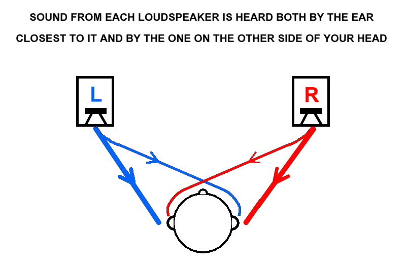
We grew accustomed to hearing combing in our day to day life, I bet it even plays a rather large role in our perception of the world around us. Good to avoid it as much as we can though in our speakers. While I think it is acting a bit different with these floor/ceiling arrays than most assume it is, personally I've never denied it's existence.
That prediction doesn't look far off.
Last edited:
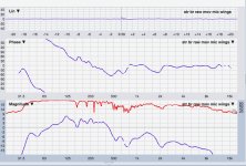
Mark, referencing post 122: if the third image is your measured FR in front of the arrays, then that is the sound you are going to hear, which is to say it is not going to sound very good. First, I would get out of measuring exactly on axis in the corner because it will introduce a cavity dip from not having the drivers all the way in the apex of the corner. I would measure closer to your listening position and try to adjust the response close to a B&K curve with all the sound included (no FDW or any other filtering). Try that first and see where it gets you.
I would not get too hung up on REW's phase response. Sometimes I go back to Holm to see the phase response because what I get in REW does not make sense. Anyway, phase response is not so important for this design, so, don't worry about it.
Also, what is the red trace in the magnitude chart?
I would not get too hung up on REW's phase response. Sometimes I go back to Holm to see the phase response because what I get in REW does not make sense. Anyway, phase response is not so important for this design, so, don't worry about it.
Also, what is the red trace in the magnitude chart?
Good stuff gentlemen !
nc535, I agree that math is the answer we can't debate...
I think rules of thumb are just judgement points about when and how much the math matters to our objectives... and lord knows that's debatable !
wesayso, I'm seeing what you mean about the side wall reflections needing to be eliminated, particularly from vertical ridges running parallel to the line array.
Yesterday, I started to get semi decent looking tuning from the corner placement, but with alot of chaos at certain frequences looking at Smaart's live transfer. And REW's spectrograph would show disjointed activity at those chaotic frequencies. So I went outside and the chaos ended....and then I knew to start playing with the room. REW's spectrograph has been really useful finding the reflections.
I have a foam topper and sleeping bag on the walls next to the array, which also has the foam board wings in place.
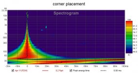
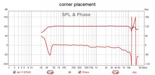
Attached plots are below. I feel like I'm beginning to get somewhere.
Biggest problem is that REW doesn't like Smaart being around in my 'puter even after I close it....I get pops during the REW sine sweep, and phase goes truly wonky, until I go through a full reboot process????
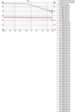
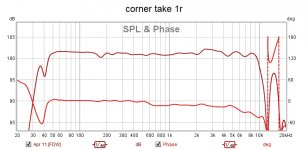
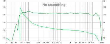
ra7, those plots in post 122 were raw response without any tuning.
At that time i was just trying to understand combing in light of the 1/2WL "rule of thumb" and corner placement.
The red trace is coherence, or how good the data is in terms of output matching input signal. It's a great indicator of how much of the room is getting into the measurement, or multiple signal sources.
It's really cool to see how high coherence is in the lower frequencies...tells me the floor to ceiling 'infinite line theory is working
Confession.....I can't help but sweat phase Lol...i've been a near fanatic / loony tunes preacher about achieving linear phase for several years. I believe it's the magic sauce haha, in how my 4-ways sound...most dynamic sound I've ever heard
nc535, I agree that math is the answer we can't debate...
I think rules of thumb are just judgement points about when and how much the math matters to our objectives... and lord knows that's debatable !
wesayso, I'm seeing what you mean about the side wall reflections needing to be eliminated, particularly from vertical ridges running parallel to the line array.
Yesterday, I started to get semi decent looking tuning from the corner placement, but with alot of chaos at certain frequences looking at Smaart's live transfer. And REW's spectrograph would show disjointed activity at those chaotic frequencies. So I went outside and the chaos ended....and then I knew to start playing with the room. REW's spectrograph has been really useful finding the reflections.
I have a foam topper and sleeping bag on the walls next to the array, which also has the foam board wings in place.
Attached plots are below. I feel like I'm beginning to get somewhere.
Biggest problem is that REW doesn't like Smaart being around in my 'puter even after I close it....I get pops during the REW sine sweep, and phase goes truly wonky, until I go through a full reboot process????
ra7, those plots in post 122 were raw response without any tuning.
At that time i was just trying to understand combing in light of the 1/2WL "rule of thumb" and corner placement.
The red trace is coherence, or how good the data is in terms of output matching input signal. It's a great indicator of how much of the room is getting into the measurement, or multiple signal sources.
It's really cool to see how high coherence is in the lower frequencies...tells me the floor to ceiling 'infinite line theory is working
Confession.....I can't help but sweat phase Lol...i've been a near fanatic / loony tunes preacher about achieving linear phase for several years. I believe it's the magic sauce haha, in how my 4-ways sound...most dynamic sound I've ever heard
Attachments
Last edited:
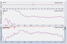
Mark, can you post the "tuned" in-room measurement?
Also, those graphs you just posted have massive scale. Can you post the first graph with a 5 dB per div scale and from 20 Hz to 20 kHz?
Hi ra7, that was the 'tuned in-room' measurement ....
here it is as requested
Attachments
Last edited:
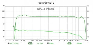
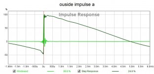
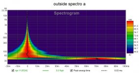
Hi all, me being me, I had to try to try a quick tuning session outside...
here's a few graphs
I'm going to listen outside the rest of the day.
Then tomorrow, I'll listen to how that tuning sounds indoors in the corner, using only high and low shelving to adjust tone.
That's kinda my standard operating procedure.
I'd like to compare that SOP vs specific tuning to a spot..
Will report listening impressions
Attachments
...Will report listening impressions
Hi Mark while that flat phase at lows looks you probably prepare for a linear phase XO point to a sub down the road, in meantime will think without that sub sound from line should be much better and natural 3d when phase is minimum rule as below
Attachments
Hi Mark while that flat phase at lows looks you probably prepare for a linear phase XO point to a sub down the road, in meantime will think without that sub sound from line should be much better and natural 3d when phase is minimum rule as below
Hi BYRTT, yes, you correctly anticipate I plan a flat phase tie in to a sub.
And you also raise one of the most interesting questions around imo.....that being, what type phase sounds best down low?
My current opinion is that it depends on how a recording was made....
I think if made on flat phase sub monitors, we want flat phase tuning.
I think if made on min phase monitors, min phase tuning...
I mean, kinda simple really...other than how the hell was it actually recorded, ie how many min phase orders of crossover were used, or is it an enlightened studio using lin phase??? haha
But for me, I hear so much extra bass definition saying 'goodbye group delay' hello flat phase, I don't care anymore. If a song was recorded with excessive group delay, well, can't win em all.....most songs rock flat phase to my ears
I really believe ditching min phase down low is part of the new magic coming to us all...
Have you seen the new breed of monitors like Meyer's bluehorn? I'm in
See, like i was saying to ra7...a lin phase zealot
 lol
lol
Last edited:
- Status
- This old topic is closed. If you want to reopen this topic, contact a moderator using the "Report Post" button.
- Home
- Loudspeakers
- Full Range
- Line array steering ?