Update on the Victor oscillator- Running overnight the distortion seems to have dropped. The second harmonic is now almost -140 dB. the higher are still lower in level at around -150 dB. I'll try to check the calibration at these low levels to make sure there is no nonlinearity affecting the readings. The Shibasoku AG16 is a little better but not much better. Essentially these are "perfect" oscillators for virtually any application.
The second harmonic is now almost -140 dB. The higher are still lower in level at around -150 dB.
How come that you can measure -140 and even -150 dB with any certainity? This would mean that the notch filter you're using has -160 dB or less distortion contribution--a quite unrealistic assumption...
Samuel
You are certainly welcome to one of my pcb's, but I am no DaVinci when it comes to circuit boards (see post 180). If you could just cover the incremental cost...
Thanks for the offer! I have the facilities to make PCBs, so it's just the laying out I'm hoping to avoid duplicating unnecessarily.
I was attracted also to DDB's Eagle layout (thanks, DDB!). I've downloaded Eagle and can open the layout in it, but I can't immediately see how to print only the copper layer. Anyone able to enlighten me? I can see how to invert or mirror the artwork to suit the PCB production method in use. But how do I turn off topside components etc? Doesn't seem to get a mention in Help.
Incidentally, DDB, you mentioned using 7 spot frequencies. Which ones did you settle on? I'm still agonising!
Terry
Last edited:
Hi TerryI was attracted also to DDB's Eagle layout (thanks, DDB!). I've downloaded Eagle and can open the layout in it, but I can't immediately see how to print only the copper layer. Anyone able to enlighten me? I can see how to invert or mirror the artwork to suit the PCB production method in use. But how do I turn off topside components etc? Doesn't seem to get a mention in Help.
Incidentally, DDB, you mentioned using 7 spot frequencies. Which ones did you settle on? I'm still agonising!
Terry
To turn off all but the bottom tracks in Eagle, click on the display icon in the left toolbar, the multicolored button under the one that looks like an i. Click on none, then click on 16,17,18 and then OK. Should see only the bottom layer.
I am using 20,100,1K,5K,10K,20K and 100K in my filter on two Alpha double deck 3-pole 4-position switches from Mouser.
HTML:
http://www.mouser.com/Search/ProductDetail.aspx?R=SR2921F-0304-19R0B-E9-S-Wvirtualkey14860000virtualkey105-SR2921F-34SHow come that you can measure -140 and even -150 dB with any certainity? This would mean that the notch filter you're using has -160 dB or less distortion contribution--a quite unrealistic assumption...
Samuel
To bracket a min/max error you would have to rule out fortuitous cancellation, but in this case I don't see the need for certainty just a max limit. Yes you would be hard pressed to make a passive notch (let alone an active one) that would tell you if it was -145dB vs -148dB.
Last edited:
The Shibasoku 725 http://www.shibasoku.com/download/avc/ad725d_e.pdf is a pretty remarkable instrument. It has a distortion analysis output that has only the harmonics without the noise. I don't know how they do it. I'm looking at the harmonics on a spectrum analyzer not THD or THD + N. I will try to check the accuracy at such low levels. I may not be too successful. The point being that whatever it is, its low enough to not affect distortion measurements on any normal audio device. Its also a remarkable indication of the linearity of modern opamps.
The Shibasoku 725 http://www.shibasoku.com/download/avc/ad725d_e.pdf is a pretty remarkable instrument. It has a distortion analysis output that has only the harmonics without the noise. I don't know how they do it. I'm looking at the harmonics on a spectrum analyzer not THD or THD + N. I will try to check the accuracy at such low levels. I may not be too successful. The point being that whatever it is, its low enough to not affect distortion measurements on any normal audio device. Its also a remarkable indication of the linearity of modern opamps.
I bet price is commensurate with performance then. I think if I could afford one of these or an AP System One, I wouldn't bother with anything else.
3K spike
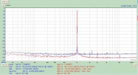
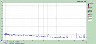
My 1KHz version came in yesterday so I ran a couple plots on my system using a Audiophile M192 in loop-back and with the oscillator for comparison.
The Oscillator is not in a chassis yet, so hopefully that will explain some of the noise.
Cables are RG174U for each signal in diff mode (8 coax total). The unused input signal on the rt channel is grounded at the oscillator.
The highest level I could get out of the M192 is -7dBfs ref 2.828V, so I adjusted the oscillator to the same level.
First plot is L- M-Audio, R - Oscillator both at -7Dbfs
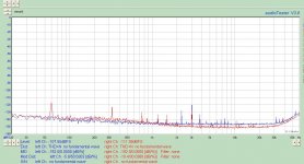
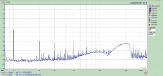
Second plot is with the output of the M192 off and the Oscillator un-powered.
The 3KHz spike is from some unknown source. I tried setting the M-192 to 10KHz and the spike remained at 3KHz.
My 1KHz version came in yesterday so I ran a couple plots on my system using a Audiophile M192 in loop-back and with the oscillator for comparison.
The Oscillator is not in a chassis yet, so hopefully that will explain some of the noise.
Cables are RG174U for each signal in diff mode (8 coax total). The unused input signal on the rt channel is grounded at the oscillator.
The highest level I could get out of the M192 is -7dBfs ref 2.828V, so I adjusted the oscillator to the same level.
First plot is L- M-Audio, R - Oscillator both at -7Dbfs
Second plot is with the output of the M192 off and the Oscillator un-powered.
The 3KHz spike is from some unknown source. I tried setting the M-192 to 10KHz and the spike remained at 3KHz.
Attachments
Hi Terry
To turn off all but the bottom tracks in Eagle, click on the display icon in the left toolbar, the multicolored button under the one that looks like an i. Click on none, then click on 16,17,18 and then OK. Should see only the bottom layer.
Beautiful, thank you. I'd guessed it might have been something to do with turning off unwanted features, but the vast number of features daunted me. The "none" trick is very good. Glad I asked!
I am using 20,100,1K,5K,10K,20K and 100K in my filter on two Alpha double deck 3-pole 4-position switches from Mouser.
Wow. You clearly subscribe to the beyond-audibility-is-important camp! Hmmm, is there a below-audibility-is-important-too camp?
On that topic, I was surprised when we built some condenser microphones for the community radio station I worked at to see significant levels on the VU meters when the mics were opened but nobody spoke. It turned out to be very significant levels of 17Hz from the studio air conditioner, even though this was mounted about 20M away and connected via lined ducts. It was easily dealt with by low cut filters which we found were necessary anyway to prevent resonant male voices sounding too boomy.
I can post some pix later his weekend if you want to see it.
Yes please!
Terry
Wow. You clearly subscribe to the beyond-audibility-is-important camp! Hmmm, is there a below-audibility-is-important-too camp?
I can hear to .01 Hz.
Does that count? Usually there is no meaningful information that low.
But it can be recorded and cause havoc.
I usually test at 2Hz.
This also exercises the power supply.
I don't see the need for certainty just a max limit.
I was referring to the (un)certainity of the end result, not the (un)certainity of the notch filter distortion contribution. Yes, an upper limit for this is surely sufficient.
Samuel
Those who are looking for a simple high-performance sinusoidal source should give a try to the venerable HP239A/339A Bridged-T generator - despite the simplicity of the design its performances are quite amazing: my (slightly modified) implementation only employs a couple of OPA2134s and a TL082, and is capable of ~0.00004% THD @ 1kHz, 20Vpp out. I think that better opamps and an ALC loop optimized for fixed frequency generation (instead of 10 Hz - 100 kHz continuous coverage) could further improve THD and THD+N figures.
Ciao,
L.
Ciao,
L.
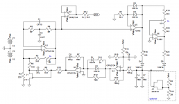
I have also built a HP339A version similar to Modifications: Heathkit IG-18 Audio Generator using a pc board.Those who are looking for a simple high-performance sinusoidal source should give a try to the venerable HP239A/339A Bridged-T generator - despite the simplicity of the design its performances are quite amazing: my (slightly modified) implementation only employs a couple of OPA2134s and a TL082, and is capable of ~0.00004% THD @ 1kHz, 20Vpp out. I think that better opamps and an ALC loop optimized for fixed frequency generation (instead of 10 Hz - 100 kHz continuous coverage) could further improve THD and THD+N figures.
Ciao,
L.
Can you post your schematic so we can see your mods?
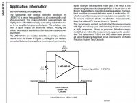
Has anyone tried this technique for measuring distortion on differential input amplifiers? I don't know if it could be used for other kinds of amps. Substitute our low distortion oscillator for the source and a super nice ADC/computer for the analyzer input.
Attachments
Last edited:
Can you post your schematic so we can see your mods?
Nothing really special - I did add a full-wave peak detector with diode-drop compensation, reworked a bit the ALC loop time constant, and employed a not-so-hard to find FET as gain controlling element. The clone seems to work just a little bit better than the original one - if I remember well the operating AC Vds of the J111 is slightly less than 80 mVpp @ 1kHz, and the level of the higher harmonic (II) is about -135 dBV, more than 100 dB below the fundamental, which seems to account for the very low output THD I see with my notches.
Ciao,
L.
Attachments
Has anyone tried this technique for measuring distortion on differential input amplifiers? I don't know if it could be used for other kinds of amps. Substitute our low distortion oscillator for the source and a super nice ADC/computer for the analyzer input.
Pease wrote a related app note too, but this technique is pretty old. You can also obviate somewhat the need for a super oscillator.
Steve Lafferty has modded a Heath IG-18 to the HP 339A circuit with the HP cap ratio of 100:1. I've modded an IG-18 to the HP 339A circuit, too, then remodded using the stock Heath caps and range switch. The results are very good. See my page IG-18 #4, the IG-339B. My page has a link to Steve's page as well.
@TerryQuote:
I can post some pix later his weekend if you want to see it.
Yes please!
Terry
Here is a couple of pix
Attachments
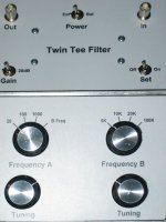
So I received Victors’ 1 kHz oscillator yesterday, and completed a first round of testing. I also built a twin-t notch filter in a separate box, to test out the real distortion of this and other sources. It is a passive design on the front end followed by a fixed gain amplifier of 100 (+40dB).
I have performed no real calibrations or loopbacks; this is just to see if things are functional or not. I have good confidence in my M-Audio Profire 610 (other than Win7 frustration) so cursory results are very encouraging.
As far as the oscillator, I built my own 35V non-regulated outboard power supply, which was actually putting out closer to 37V at 35mA. This caused the oscillator’s local power supply to run a little too warm for my comfort; you could really see drift of circuit performance as the entire pcb warmed up. The TL431’s were running around 55-60C absolute. So a 100 ohm resistor in series was sufficient to bring voltage down to 34.7V, where the shunt power supply was much more happy and cooler.
Frequency of oscillation was 1001.2 Hz, well within specifications. Ideally let the assembly run for 15-20 minutes before doing any serious measurements. Gain control appears very decent- I had the Fluke 87 bouncing +/-1mV, but that could just be the meter itself. It doesn’t appear to have a significant effect on distortion results, anyway.
Now that I knew the oscillator’s frequency, I could custom tailor my notch filter specifically to that frequency, getting maximum performance. Happy to report, that worked out really well- I was able to get a -82dB notch, which followed by the +40dB fixed gain amplifier resulted in total fundamental attenuation of -42dB. Now I had a low fundamental, which would not (probably) add any distortion products on the soundcard’s FFT results. Any distortion I see would now be from the oscillator and notch filter. Although the notch tends to drift a little with time, all I was interested in was getting it low enough to not be an issue with the soundcard; I believe I have accomplished that.
So by the numbers, my low-Q notch filter performs as follows:
2nd: +30.9 dB
3rd: +34.9
4th: +36.7
5th: +37.7
6th: +38.3
7th: +38.7
8th: +39.0
9th: +39.2
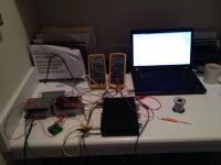
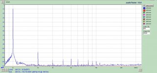
I set the oscillator for around 2V rms output (-9dBFS) and began measurements. Keep in mind, this is a mess of wiring at present; I have attached a picture showing the spaghetti setup, so you understand that a little noise here and there is expected. Pre-notch into the soundcard and post-notch into the soundcard attached. My observation:
2nd harmonic (which has been boosted by 30.9 dB by the notch filter) is actually at -137 dB below the fundamental.
3rd unmeasureable.
4th at -147 below fundamental.
5th at -inf.
6th at -145.
7th at -inf.
8th at -141.
THD therefore 0.000018%
The pre-notch capture indicates to me that in the presence of a strong fundamental, the soundcard does in fact distort, resulting in erroneous measurements of harmonics. So a notch filter is absolutely required in order to test the distortion of Victor’s oscillator, and for the price, that’s a darn nice oscillator.
Your thoughts?
I have performed no real calibrations or loopbacks; this is just to see if things are functional or not. I have good confidence in my M-Audio Profire 610 (other than Win7 frustration) so cursory results are very encouraging.
As far as the oscillator, I built my own 35V non-regulated outboard power supply, which was actually putting out closer to 37V at 35mA. This caused the oscillator’s local power supply to run a little too warm for my comfort; you could really see drift of circuit performance as the entire pcb warmed up. The TL431’s were running around 55-60C absolute. So a 100 ohm resistor in series was sufficient to bring voltage down to 34.7V, where the shunt power supply was much more happy and cooler.
Frequency of oscillation was 1001.2 Hz, well within specifications. Ideally let the assembly run for 15-20 minutes before doing any serious measurements. Gain control appears very decent- I had the Fluke 87 bouncing +/-1mV, but that could just be the meter itself. It doesn’t appear to have a significant effect on distortion results, anyway.
Now that I knew the oscillator’s frequency, I could custom tailor my notch filter specifically to that frequency, getting maximum performance. Happy to report, that worked out really well- I was able to get a -82dB notch, which followed by the +40dB fixed gain amplifier resulted in total fundamental attenuation of -42dB. Now I had a low fundamental, which would not (probably) add any distortion products on the soundcard’s FFT results. Any distortion I see would now be from the oscillator and notch filter. Although the notch tends to drift a little with time, all I was interested in was getting it low enough to not be an issue with the soundcard; I believe I have accomplished that.
So by the numbers, my low-Q notch filter performs as follows:
2nd: +30.9 dB
3rd: +34.9
4th: +36.7
5th: +37.7
6th: +38.3
7th: +38.7
8th: +39.0
9th: +39.2
I set the oscillator for around 2V rms output (-9dBFS) and began measurements. Keep in mind, this is a mess of wiring at present; I have attached a picture showing the spaghetti setup, so you understand that a little noise here and there is expected. Pre-notch into the soundcard and post-notch into the soundcard attached. My observation:
2nd harmonic (which has been boosted by 30.9 dB by the notch filter) is actually at -137 dB below the fundamental.
3rd unmeasureable.
4th at -147 below fundamental.
5th at -inf.
6th at -145.
7th at -inf.
8th at -141.
THD therefore 0.000018%
The pre-notch capture indicates to me that in the presence of a strong fundamental, the soundcard does in fact distort, resulting in erroneous measurements of harmonics. So a notch filter is absolutely required in order to test the distortion of Victor’s oscillator, and for the price, that’s a darn nice oscillator.
Your thoughts?
Attachments
For kicks, I measured the output of my DCX2496 (1.65V rms) , which is modded by using a Jensen JT-11-DMPC directly connected to the D/A pins. Significantly higher distortion than Victor’s (though still not too bad):
2 = -99 dB
3 = -107
4 = -123
5 = -109
6 = 0
7 = -121
THD = 0.0013%
2 = -99 dB
3 = -107
4 = -123
5 = -109
6 = 0
7 = -121
THD = 0.0013%
Attachments
- Home
- Design & Build
- Equipment & Tools
- Low-distortion Audio-range Oscillator