Hi guys.
Did you have a look at the "Asynchronous I2S Fifo" thread over at the Digital Line Level forum section?
Lot's of interesting and related info. He claims that different inputs (he's using a DIR9001 as SPDIF receiver afaik) wouldn't
make a difference with his solution anymore.
I'm wondering if something like that Fifo functionality is already or could be introduced to your
design!?!? One wouldn't need a seperate FPGA board if the receiver chip would be able
manage it all. However...
...on the other hand a 2-stage approach "USB-receiver + seperated I2S Fifo" would allow for isolators in between.
The intrisic jitter of those isolators wouldn't really matter anymore, because the FIFO would be able to clean up this jitter.
The guy uses batteries to power his device. USB receiver and FIFO supplies could be kept 100% seperate using that approach.
You might be able to use bus-power for the receiver in this case and batteries for the FIFO and clock..
All that sounds really promising to me. You might get in touch with him -- at least on certain parts. 😉
I do have a feeling that a combination of both approaches would be the potentially best solution
around and would solve a lot of issues.
Cheers
Last edited:
this is just plain nonsense. Perhaps you have not clearly understood how digital audio systems works and what can be their pitfalls. Let me try to explain.To me above thinking incorporates a big mistake.
Jitter sources must be avoided as far upstream as possible.
Except perhaps at huge, pathological levels, jitter does NOT affect digital data transmission integrity (and this is not what we're talking about). Even with a link as bad as s/pdif and a jittery source, if the source sends "1234" the receiver still gets "1234".
The only places where jitter does matter are those places where data samples AND timing information are somehow combined together, either to calculate new data sample values (ASRC) or to recreate an analog signal (DAC).
In many (most) existing solutions the master clock is either at the data stream source or somewhere in the middle of the stream path.
Examples could be the typical CD transport + DAC (master clock at the source) and USB interfaces such as the hiFace (where the master clock is in the interface itself, that is "in the middle").
Of course, with this arrangement the DAC clock have to be somehow slaved to that master clock.
This is inherently, conceptually wrong.
In such situations, what you say can be true: the jitter of the master clock is propagated down the line and combined with that of the slave clock(s) (e.g. by PLLs) and/or embedded into the new data samples by ASRCs.
The resulting jitter on the clock used by the DAC and/or errors in the data introduced by jittery input to ASRC will eventually affect the reconstructed analog signal.
Audio Widget is different. It is designed from the ground up in the right way: the master clock is right on the DAC side and everything else is slaved to it.
It is NOT the I2S clock (and its jitter) that rules the DAC, but the other way around: it's the DAC clock that "drives" the I2S. Jitter on the I2S bus does not affect the timing information used for d/a conversion. That is, jitter on I2S does not (can not) affect the d/a conversion in any way.
That's why, as Børge suggested, you may safely add optocouplers (which are inherently jittery...) in the middle of the I2S bus. In most other systems, doing so would likely be a solution worse than the problem they'd called to solve. But NOT on the AW.
Here only the local DAC clock provides the timing information for d/a conversion. Thus it's only the local clock jitter that matters.
The only remaining pitfalls can be EM noise and any other unwanted interaction between different part of the circuit which may somehow affect the local DAC clock oscillator and/or the DAC itself.
That's why layout, good and independent local power supplies, maximum possible isolation of the sensible parts (DAC and its clock) from the "dirty" side (host computer, USB, MCU), etc, are paramount.
And that's why the optocouplers idea is IMHO a very good one.
If properly implemented, completely isolating the sensible parts from all the rest should solve the remaining problems and thus may make a huge difference.
P.S.: now that I think about it, I have a question. AFAIK the Sabre input uses an ASRC. Is there an internal FIFO to buffer and reclock the I2S according to the local clock before passing the stream to the internal ASRC? otherwise, an external FIFO reclocker must be added on the I2S bus! (even if not using optocouplers!)
Last edited:
P.S.: now that I think about it, I have a question. AFAIK the Sabre input uses an ASRC. Is there an internal FIFO to buffer and reclock the I2S according to the local clock before passing the stream to the internal ASRC? otherwise, an external FIFO reclocker must be added on the I2S bus! (even if not using optocouplers!)
Isn't that only required if the ASRC derives its incoming clock from data? If master clock is used, then the ASRC interpolation will be based on master clock and thus "reclocked" correctly.
That's why layout, good and independent local power supplies, maximum possible isolation of the sensible parts (DAC and its clock) from the "dirty" side (host computer, USB, MCU), etc, are paramount.
Yep.
If properly implemented, completely isolating the sensible parts from all the rest should solve the remaining problems and thus may make a huge difference.
Complete isolation? So that no signals get through at all? Surely you don't mean that - rather you mean maximum possible isolation commensurate with still functioning properly. In which case agreed - but that's what people have been working towards for many years. The isolation factor is paramount and its never going to be complete, hence the ongoing discussion.
Complete electrical isolation is worth trying out.
Anybody who wants to try out this (or other analog consepts) is very welcome to do so. Tweak the AB-1.1 with all you've got and tell us about the result.
Cheers,
Børge
Anybody who wants to try out this (or other analog consepts) is very welcome to do so. Tweak the AB-1.1 with all you've got and tell us about the result.
Cheers,
Børge
Yep.
Complete isolation? So that no signals get through at all? Surely you don't mean that - rather you mean maximum possible isolation commensurate with still functioning properly. In which case agreed - but that's what people have been working towards for many years. The isolation factor is paramount and its never going to be complete, hence the ongoing discussion.
nice one.Did you have a look at the "Asynchronous I2S Fifo" thread over at the Digital Line Level forum section?
no need for such complication: AW is already 100% asyncronous. Optoisolation can be safely added in the middle of the I2S bus. All that may be needed (if it's not already included in the Sabre input) is a simple FIFO buffer (actually just a latch)....on the other hand a 2-stage approach "USB-receiver + seperated I2S Fifo" would allow for isolators in between.
not sure about that, but I'm no ASRC expert at all. If someone has better cue and explanation, please tell us!Isn't that only required if the ASRC derives its incoming clock from data? If master clock is used, then the ASRC interpolation will be based on master clock and thus "reclocked" correctly.

AFAIK, ASRCs makes no errors only if both the incoming and the local ("output") clocks are synchronous with each other and jitter free (that is, when they are basically useless... 😱 ).
Indeed, given that in AW the I2S signal is synchronous with the local clock and thus the ASRC can be (it is) clocked from the clean local clock, perhaps jitter on the I2S (data) lines does not matter.
Hints, anyone?
Hi Paolo,
I believe jitter on the I2S lines don't matter. Period. As long as digital signal integrity is OK (i.e. signals latched on correct clock edges), the FIFO / SIPO / other digital stuff in the DAC should be doing just fine. In fact it may even be good with a bit of jitter to spread the spectrum.
Where jitter really does matter is when the DAC moves its internal digital signal onto a switched current generator or R2R ladder. This is the first time the signal becomes analog, and this is a process which must happen with the smallest possible time-domain variations. (And of course, the current generators etc. must be precise in the current or voltage domain.)
Børge
😀Complete isolation? So that no signals get through at all?
of course, I mean complete electrical isolation. That's what an optoisolator would (almost perfectly) do.
A relatively long optical link using optical fiber would be even better (it would completely avoid any parastitic coupling...), but it would be complex, expensive and not very practical to use on the many I2S lines.
A great thing would be to use an optical USB3 link, if it will ever be available (perhaps in addition to the optoisolators on the I2S bus to keep also most of the locally generated noise out of the way).
Last edited:
My friend compared the audio-gd shunt with LifePO4 on another ES9023 based on Hiface interface, the difference is like a tube vs SS amplifier, shunt bring in warmth without losing any detail.
Will be interesting to compare SQ between Salas shunt and LiFePO4 🙂
Alex
Attachments
Last edited:
I've always wondered about shunts. Do they work because they have low output impedances to the load? Personally I believe it might be because they only draw DC from the PCU, not signal correlated current.
I think one of the benefit of shunt regulator is ultra low impedances comparing to battery. The noise level at 5V is around 30nV according to the Salas shunt forum. With CCS in series, it has very good PSRR as well.
Trident shunt in Buffalo DAC uses the shunt part only without a CCS with good result, now it's a standard in Buffalo III.
Shunt Regulation - diyAudio
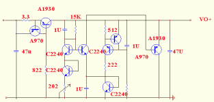
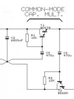
I also attached the salas shunt I am using with common mode cap multiplier at the front.
Trident shunt in Buffalo DAC uses the shunt part only without a CCS with good result, now it's a standard in Buffalo III.
Shunt Regulation - diyAudio
I also attached the salas shunt I am using with common mode cap multiplier at the front.
I've always wondered about shunts. Do they work because they have low output impedances to the load? Personally I believe it might be because they only draw DC from the PCU, not signal correlated current.
Attachments
Last edited:
I guess you mean that only relatively to the specific configuration used in AW? 😕I believe jitter on the I2S lines don't matter. Period. As long as digital signal integrity is OK (i.e. signals latched on correct clock edges), the FIFO / SIPO / other digital stuff in the DAC should be doing just fine.
More as a general rule, actually. First of all know your DAC and which signal makes it latch internally. Then optimize that signal for jitter and everything else for integrity.
Hi Borge,
Does the enclosure have enough space to fit the Salas shunt in? Will need to drill another hole in your enclosure for the +9V DC in though 🙂
Alex
Does the enclosure have enough space to fit the Salas shunt in? Will need to drill another hole in your enclosure for the +9V DC in though 🙂
Alex
I definitely second this idea.Personally I believe it might be because they only draw DC from the PCU, not signal correlated current.

Shunts also allow for hi-impedance between raw PSU and load. I guess the best possible PSU should be made with a simple series CCS (a couple of cascoded depletion MOSFETs...) followed by something like a Salas shunt reg (in parallel with a good and properly dimensioned by-pass C, too!).
The series CCS will completely decouple the load from the raw PSU and force the load AC currents circuit to entirely close within a short, local loop. With only DC currents on ground and supply lines (outside of the local loop).
Every single load in any audio-related circuit should be powered this way!

Of course also low impedance on the load side is a good thing (and a good regulator is usually better than a naked battery WRT this parameter). But that's not an exclusive feature of shunt regs. Good series regs may also sport very low output impedances...
BTW: regardless of the type and technology used, IMO the regulator "bandwidth" - that is it's ability to remain stable and keep the supply line clean WRT high freq. components of the load current - is paramount.
For instance, many (most?) integrated regulators which use op-amps and lot of NFB shows great numbers "@DC" but actually have a very limited bandwidth. As soon as the frequency rise, their characteristics (output impedance, etc) decay dramatically. IMO, such kind of regulators are basically useless if not detrimental (that's why I prefer simple circuits...).
Hi Alex,
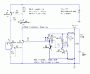
Have a look at this picture. When I had the boards made, the USB-I2S module popped out of the void. The outer size of the void is 71x62mm. Minus the 15x15 rectangle. Even outside this area it is possible to expand the opening. The height inside the box is 29mm.
Børge
Have a look at this picture. When I had the boards made, the USB-I2S module popped out of the void. The outer size of the void is 71x62mm. Minus the 15x15 rectangle. Even outside this area it is possible to expand the opening. The height inside the box is 29mm.
Børge
Attachments

Using ccs/shunt with XO is almost a must, it improves sound dramatically. I got moderate improvement feeding ccs/shunt to DAC and MCU. It may be a good idea put a shunt only (similar to twistpearaudio trident) after ADP151 (good PSRR, regulated at higher vol, ex 4.5V) so we can still use USB power. I am not sure if we can design a good CCS with low dropout of 1.7V (5v-3.3v) and good PSRR to work with shunt.
Hi Borge,
Does the enclosure have enough space to fit the Salas shunt in? Will need to drill another hole in your enclosure for the +9V DC in though 🙂
Alex
Last edited:
- Home
- Source & Line
- Digital Source
- Open-source USB interface: Audio Widget