FIRST OSCILLOGRAMS D-I NOS-DAC! (2)
Second picture
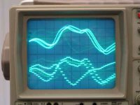
Here are the first oscilloscope pictures of the Direct Interpolation NOS-DAC, compared to a reference NOS-dac
Note it is very difficult to photograph real-time audio signals on an oscilloscope, so this is only to give an impression.
Upper trace: Direct Interpolation NOS-dac (Quad version) unfiltered!
Lower trace: Reference NOS-dac unfiltered!
Notice the difference in resolution!
Note: the addittional line in the lower trace is caused by the "alternate" mode of the oscilloscope
Second picture
Here are the first oscilloscope pictures of the Direct Interpolation NOS-DAC, compared to a reference NOS-dac
Note it is very difficult to photograph real-time audio signals on an oscilloscope, so this is only to give an impression.
Upper trace: Direct Interpolation NOS-dac (Quad version) unfiltered!
Lower trace: Reference NOS-dac unfiltered!
Notice the difference in resolution!
Note: the addittional line in the lower trace is caused by the "alternate" mode of the oscilloscope
Attachments
Re: re pictures
I'd be surprised if it didn't.
Be interesting to see an 18 or 19k sinewave though.
poynton said:Well, it seems to work !
I'd be surprised if it didn't.
Be interesting to see an 18 or 19k sinewave though.
Ec designs: Why is a delay per dac of 4 clockcycles (with 4 dacs) not the same as in your setup with four dacs. I know the I2S wordlenght is 32 bit, 16 bit audio and 16 bit subcode data. The dac doesnt use the subcode data, so why is exactly would my logic work inferior to yours. (not offending ment 😉 )
The oscilloscope graphs show a lot! , i can imagine the sound is more detailed now, and i think some very quiet sounds are lifted out of the digital noise.
And i agree: the sound of it is the most important, thats where you listen to.
The oscilloscope graphs show a lot! , i can imagine the sound is more detailed now, and i think some very quiet sounds are lifted out of the digital noise.
And i agree: the sound of it is the most important, thats where you listen to.
in phase
Hi, ezkcdude,
thanks for your reply,
I Hooked both my reference DAC and the new quad D-I DAC to the CD player (SPDIF). Connected L output of reference DAC to lower channel and the L output of the D-I DAC to the upper channel, that's it. The oscillogram shows that both are in phase, so no significant phase shift as I mentioned in earlier posts.
(Both DAC's run on 44.1 KHz of course)
High frequency signals
Hi, rfbrw
Thanks for your reply,
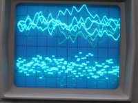
Of course you (and poobah) want to know what happens with higher frequencies. I will do some tests later (need a good sampled 18 KHz sinewave recording first). But, what I do have is a oscillogram of white noise from a test CD. Perhaps that gives an impression of high frequency response.
Hi, rfbrw
Thanks for your reply,
Of course you (and poobah) want to know what happens with higher frequencies. I will do some tests later (need a good sampled 18 KHz sinewave recording first). But, what I do have is a oscillogram of white noise from a test CD. Perhaps that gives an impression of high frequency response.
Attachments
ec,
I think we are only saying that this is a mechanical way of implementing linear interpolation... it will be sublect to the same shortcomings.
I think we are only saying that this is a mechanical way of implementing linear interpolation... it will be sublect to the same shortcomings.
It is a standard linear interpolation. Perhaps its advantage compared to linearly interpolating in the digital domain is that each DAC WS frequency is 44.1kHz only?
It is also possible, and likely, that because 4 DACs are being averaged that some reduction linearity error is achieved.
😉
😉
Ecdesigns, afther re-reading this becoming huge thread, i missed something. For the Dem oscillators i fitted standard 4 470pF caps. But its a good idea to try the master-slave solution. I wanted to try the dem reclock (here on diyaudio) circuit too, but then i have build 4 of them, its not sur how 4 dacs work on 1 dem reclock schematic. What also can be done is leveling of I2S on a DC value, but then it gets all too complicated.
I am very interested in those modular pcb's to try this ultimate setup. If i get 2 1541's extra, could build it with 8 dacs.
I am very interested in those modular pcb's to try this ultimate setup. If i get 2 1541's extra, could build it with 8 dacs.
Advantages Direct Interpolation
Hi, phofman,
Thanks for your reply,
I still get the impression that there is some confusion about the advantages of the D-I DAC and that the principle of operation is still unclear.
1) It runs at 44.1 KHz (NON-oversampling)
2) It uses NO (digital) brickwall filtering at all.
3) It causes NO "ringing" as a digital chebychev filter does.
4) The output signal is "clean" enoug to leave out the "external filter" that IS necessary with a standard NON-oversampling DAC (check your NOS-DAC diagram).
5) The phase response is LINEAR
6) It uses NO decimation (no addittional noise)
7) Amount of samples is increased (smoother signal, mirror image is moved upwards to a higher frequency region, ultrasonic interference is greatly reduced)
8) Analog resolution increases (smoother steps as there are intermediate steps now, theoretically 19 bit resolution with an octal D-I DAC version)
>The aim of this tread is to build an ultimate NON-oversampling DAC (improve the concept to the max) I think the D-I DAC is a good start 🙂. I am not claiming this DI-DAC is perfect but what is?
If you look at the oscillograms I posted, it's difficult to admit there is no improvement made (consider that the oscillograms show the quad DI-DAC so resolution can go even Higher).
Drawbacks:
As poobah already indicated, (linear) interpolation has it's drawbacks. You try to theoretically reconstruct something based on 16 bit samples. I agree, you never achieve the original high resolution studio quality. But you can try to come close.
A reply to the 18 KHz "issue":
A 18 KHz (20KHz) "sinewave" looks as a quarewave in the standard NOS-dac as there are only about 2 samples. And squarewaves don't sound nice.
The D-I dac outputs a triangle wave using linear interpolation and a sinewave with non-linear interpolation. You must admit that a triangle wave or sinewave sound better.
Optimizing:
By using binary coded non linear steps (different output gain at each I/V stage) the very high frequencies could be shaped like perfect sinewaves. As the audio signal consists of numerous sinewaves (fourier theorema) 20KHz being about the highest recorded with 44.1 KHz samplerate. Using non linear amplitude steps seems logical and worth investigating.
But here is an important question to you all: Who can hear the difference between a 20 KHz sinewave and a 20KHz triangle wave as they sound almost the same.
tubee said:Because of those 8 points i wanted to try a non-os four paralleled TDA1541 dac.
Me too !
Can someone produce the PCBs, please?
Andy
Ecdesigns,
Thanks for the summary. Your interesting circuit does in fact linear interpolation with 3 extra points in between regular samples. Since output currents of the DACs are adding:
at time t0 + 3/4 (with sample S0): 4 x S0
t1: 3 x S0 + 1 x S1
t1 + 1/4: 2 x S0 + 2 x S1
t1 + 2/4: 1 x S0 + 3 x S1
t1 + 3/4: 4 x S1
t2: 3 x S1 + 1 x S2
The result between (t0 + 3/4) and (t1 + 3/4) is a straight line (well, in fact 4 smaller steps instead of the one large step).
The same functionality could be implemented in digital domain with one at least 18 bit DAC only. I agree the 16bit TDA1541A could not be used, presumably resulting in a different sound than your solution.
DI-DAC PCB's
Hi poynton,
Thanks for your reply,
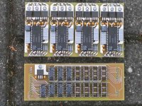
In fact somebody has already made the PCB's.... I did 🙂.
Upper PCB is the Quad-DAC module (4 separate DAC circuits), you can use two of these for an octal DAC
Lower PCB is the timing chain, the heart of the D-I DAC. It supports dual, quad and octal DI-DAC's. Well as you can see I ran out of chips...
As I already mentioned in earlier posts I plan to design a number of modules, and then when enoug people are interested, circuit boards can be manufactured. But first I plan to design the other modules, mentioned in my posts.
Hi poynton,
Thanks for your reply,
In fact somebody has already made the PCB's.... I did 🙂.
Upper PCB is the Quad-DAC module (4 separate DAC circuits), you can use two of these for an octal DAC
Lower PCB is the timing chain, the heart of the D-I DAC. It supports dual, quad and octal DI-DAC's. Well as you can see I ran out of chips...
As I already mentioned in earlier posts I plan to design a number of modules, and then when enoug people are interested, circuit boards can be manufactured. But first I plan to design the other modules, mentioned in my posts.
Attachments

Re: Advantages Direct Interpolation
I tend to disagree. No one can here the difference between a 18 kHz (if you can hear at all a sine of 18kHz) Triangle or square wave, as our ears filters all harmonics very effectively. That is why you do not use filtering at all with NOS imho....
-ecdesigns- said:
A 18 KHz (20KHz) "sinewave" looks as a quarewave in the standard NOS-dac as there are only about 2 samples. And squarewaves don't sound nice.
The D-I dac outputs a triangle wave using linear interpolation and a sinewave with non-linear interpolation. You must admit that a triangle wave or sinewave sound better.
I tend to disagree. No one can here the difference between a 18 kHz (if you can hear at all a sine of 18kHz) Triangle or square wave, as our ears filters all harmonics very effectively. That is why you do not use filtering at all with NOS imho....
Re: Re: Advantages Direct Interpolation
And there are a significant number of people who cannot hear 18kHz at all !
Andy
dddac said:
I tend to disagree. No one can here the difference between a 18 kHz (if you can hear at all a sine of 18kHz) Triangle or square wave, as our ears filters all harmonics very effectively. That is why you do not use filtering at all with NOS imho....
And there are a significant number of people who cannot hear 18kHz at all !
Andy
- Home
- Source & Line
- Digital Line Level
- Building the ultimate NOS DAC using TDA1541A