Well...this should be pinned 🙂I think I am coolest guy here on all basics man aspects(looks, physical strenght, endurance, health, sucess on womans, libido- you name it), except maybe electronics 😕 Its not my subjective opinion, I rely only on science measurements. 😀
What is really surpsising- how many middle age mans with lot of visceral fats, and low testosterone levels shows bellicosity. that is amazing. 😎
I have never had ability to brag for my achivements until today. If anyone thinks he is tougher guy than my you are welcome in discussion. I did not come here to bring any audio related jewels, just wanted to brag.
and on the seruos note-this is most interesting, valuable forum from all audio forum i have had pleasure to read. keep it up!
Dou you preffer the high resolution with low timestep version:
Sosai Masutatsu Oyama - Kata Entensho - YouTube
the low resolution with high timestep version:
Kyokushin Karate - Kata Tensho - Bobby Lowe 8 Dan - YouTube
or the lowest timestep and resolution one?
Grand Master TRAN TIEN Vietnam Kung Fu - YouTube
You choose between the french or british meaning of resolution...
You can not use FKP WIMA to filter frequencies> 10-100MHz.
Something like that
Type MLCCs
I just show Hans what to try to measure with this simulation.
It looks like people are just loosing their time with you mate!
Attachments
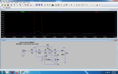
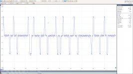
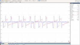
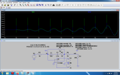
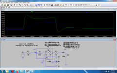
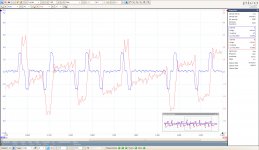
Just as some additional measurement information to what I showed earlier with both channels unfiltered, see third image, I filtered the channels @ 10Mhz, and displayed it on a 1usec/div, makes things easier to follow.
Mind the different vertical scales compared to image 3.
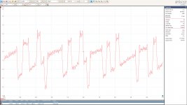
Unfortunately I cannot display both channels at the same time with the filters switched on, so here they are displayed in two separate images, again current output in 25R in blue and output of the LT1468 via the OPA1632 in red.
The current pulses are 82nsec wide as before, but now filtered from all the spikes around it.
The voltage output reacts on those pulses in the way as shown.
Hans
.
Mind the different vertical scales compared to image 3.
Unfortunately I cannot display both channels at the same time with the filters switched on, so here they are displayed in two separate images, again current output in 25R in blue and output of the LT1468 via the OPA1632 in red.
The current pulses are 82nsec wide as before, but now filtered from all the spikes around it.
The voltage output reacts on those pulses in the way as shown.
Hans
.
Attachments
Well...this should be pinned 🙂
Dou you preffer the high resolution with low timestep version:
Sosai Masutatsu Oyama - Kata Entensho - YouTube
the low resolution with high timestep version:
Kyokushin Karate - Kata Tensho - Bobby Lowe 8 Dan - YouTube
or the lowest timestep and resolution one?
Grand Master TRAN TIEN Vietnam Kung Fu - YouTube
You choose between the french or british meaning of resolution...
Dear Mr. Dreamth, all this ancient and rought evaluation of performance. its like evaluating speakers by listening to them. Bad. Today we have chose science to evalue and measure all human being performance/toughness. speed- motions per second, strenght - lifted weight. The time of samuray reaction time to enemy are long gone- we have more precise psichomotorics reaction to irritants- like reaction to light or sound or combined reaction tests. you hit the button, not the other person-much more civilized way.
since 2000 when spice came around I have yet to see any real built circuits,mainly simulations. I have built some simulated circuits here which did not worked at all.
I remember Jocko (RIP) which was lot like Sandy( except better developed sense of humor)
Banning "hard"people, and trying to make forum peacefull its like trying to achieve complete peace in jungle by teaching lions not to eat antilope. its against nature. We are born this way as other animals in this planet- we are ment to argue, disagree and fight. this is the best way to achieve complete plenitude of society and lot of good things. Moderators should encourage others to do that , and duty of normal forum mebbers to help them.
I love rought, rude people coming here and showing their works. this shows they loves other people and want to share litle part of themselves. you cant blame persons for having diferent way of loving you. what they wrote extra is not that important (for any mentaly developed and healthy adult from age 30 to 60)
again- sorry about offtopics.
Last edited:
@elviukai
"The time of samuray reaction time to enemy are long gone- we have more precise psichomotorics reaction to irritants- like reaction to light or sound or combined reaction tests. you hit the button, not the other person-much more civilized way."
Really?
Real Samurai Sword Technique - Cutting BB Gun pellet by Isao Machii - Japanese Katana Kenjutsu - YouTube
Meet A Real Samurai (Cuts 240 mph BB Gun Pellet) | EVERYDAY BOSSES #15 - YouTube
Untill you get to make peace with yourself, you can see that Hans measurements show less noise than my simulations where i tried to reduce all the reactances and inductances to your friend's standards which seem to be highly unrealistic ...
By the way...i used to fight in a real ring with no weight limit , write poetry and make translations from french for money 20 years ago...yet i preffer this dry simulation printscreens of life that hits the reality harder than 1000 words.For the fights i wasn't payed directly, but i 'd get free training ,equipment and clothes as i was fantastically poor at the time.
Last edited:
@Dreamth,
Thx for taking the trouble to simulate things.
However, unfortunately the simulations with the LT1486 do not come close to what's measured.
The other thing to mention is that the Wima FKP cap has a series inductance of ca. 10nH, much lower as what you used in your model.
Hans
Thx for taking the trouble to simulate things.
However, unfortunately the simulations with the LT1486 do not come close to what's measured.
The other thing to mention is that the Wima FKP cap has a series inductance of ca. 10nH, much lower as what you used in your model.
Hans
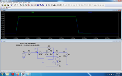
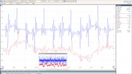
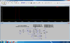
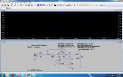
I finally managed to get the Dac output current and the I-V converter output in one image with both signals LP filtered at 10Mhz.
This makes it perfectly clear how the I-V converter reacts to current input pulses.
Hans
.
Care to explain? I have to admit I don't understand what you are showing here. Other than a loose correlation between the two signals (one appears to be loosely related to the derivative of the other). What is to be learned from these measurements?
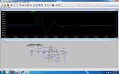
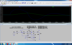
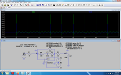
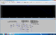
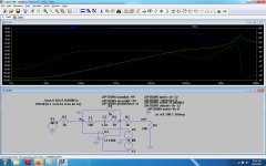
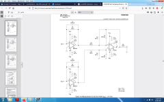
the input is a virtual ground input, the scale is 1/5 so it's still ok if measured as a voltage. i used 10nH now as Hans said...yet the reactance per wima datashheet should be about 10 ohms in total including the 2.2 ohm .It doesn't make much difference though if it's 10 ohm or 2 ohms.In Hans photo it looks like the signal area is the same on the input as on the output, but the output is on a 5 times smaller scale.In simulations I get roughly the same input and output area on the same scale, so measurements are still better than simulations if i get it right...red is the absolute input before voltage to current transformation, blue is the vrtual ground input of i/v, green the i/v output.
Attachments
Last edited:
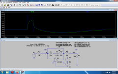
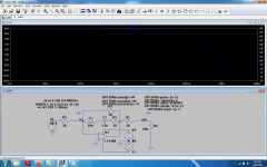
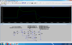
To get simillar results i need 10 pf stray capacitance everywhere which gets it peaking at 1megHz, but i'm not really confident with convergence rules manipulations to get the right result in case the model is a little bit closer to reality than expected.
Attachments

Last edited:

a i'm not much of a math guy this is a bit more confusing than i needed for my blissful mind peace 🙂
Attachments
Last edited:
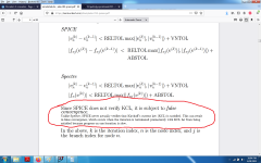
It means you can occasionally get unphysical nonsense out of simulators, and that SPICE is a bit more susceptical to that than Spectre. In particular, it may find solutions where the currents flowing into and out of a node don't add up to zero. I know from experience that it's very well possible to get crap out of Spectre as well, though.
Care to explain? I have to admit I don't understand what you are showing here. Other than a loose correlation between the two signals (one appears to be loosely related to the derivative of the other). What is to be learned from these measurements?
Yes of course. Three reasons for measuring at all:
1) To find out what signal is generated from the Dac
2) From this information get some insight at how the Dac is functioning
3) Getting some confidence whether a LT1468 or similar fast voltage feedback amp can handle this signal without input overload.
We have to go back to this posting how the measuring set-up looked like.
Discrete I-V converter
Already shown here was in blue the current output and the output of the V-I converter in red as measured on an upgoing square wave ramp.
Further to this, I also looked at both signals with the Dac in idling position.
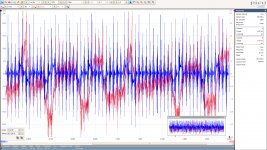
Since it is rather difficult to see what's really happening with all those spikes polluting the signal, I applied a 10Mhz LP filter on both signals.
See both images below, unfiltered and filtered.
What became clear is that the Dac, although specified as 192Khz, switches it's output current 64 times as fast at 81.38 nsec intervals and that transients while switching are in the very low nano seconds.
Question 1) and 2) are answered, but 3) still open.
Hans
.
Attachments
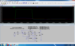
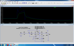
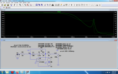
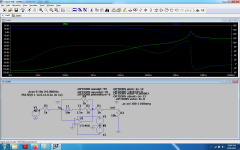
further attempts to beat the box can make you not even be able to see the ellephant in the room, but the light is off and you can only smell it...in the last picture green is the input virtual ground pin and blue is the output in sine form with 2pf stray capacitance.
Attachments
Last edited:
did you apply the 20khz differential LPF filter like in the pcm1792 data with their lt1028 or similar op-amp too?3) Getting some confidence whether a LT1468 or similar fast voltage feedback amp can handle this signal without input overload.
Since it is rather difficult to see what's really happening with all those spikes polluting the signal, I applied a 10Mhz LP filter on both signals.
See both images below, unfiltered and filtered.
What became clear is that the Dac, although specified as 192Khz, switches it's output current 64 times as fast at 81.38 nsec intervals and that transients while switching are in the very low nano seconds.
Question 1) and 2) are answered, but 3) still open.
Hans
.
Last edited:
Well this means that simulations aren't necesarilly as good as the component models are...that's a bit dissapointing, but maybe that is why real measurements and intuition are still the way to go for final adjustments, yet i'm not ready to discard simulations as most of them are still very close to reality.It means you can occasionally get unphysical nonsense out of simulators, and that SPICE is a bit more susceptical to that than Spectre. In particular, it may find solutions where the currents flowing into and out of a node don't add up to zero. I know from experience that it's very well possible to get crap out of Spectre as well, though.
I had my own take on the i/v applied to audio signals phylosophy and i really think there is a philosophy as long as both the speakers and our ears are naturally integrating most of the garbage. At some point I was in favor of no active filter at all past i/v stage , just very high speed circuits for i/v and further amplifiers down the line but now i'm thinking that it might actually be very benefficial to use the lowest slew rate op-amp that can deal with the audio range as usual rc(lc) or pi filters after i/v plus stray capacitances will be able to deal very well with any high speed signals down to the speakers and no meghertz signals will get out of any normal speaker , nor our ear will have any conideration for it.Still very confident with using the old lm833 for anything audio honestly.
Last edited:
It's in the original datasheet, page 35, 36 : https://www.ti.com/lit/ds/sles105b/sles105b.pdf?ts=1624897234700&ref_url=https%253A%252F%252Fwww.google.com%252F
I started to have some more respect for the original datasheet of components after i was made aware of Neve's RNHP sounding very well for one of the best musician's ears i know in person , the guy who finally tuned the Empyrean Meze Audio 3000 euro headphones(at least in Romania he's a well known musician), when seeing that Neve used TPA6120 and ne5534 as in the original datasheet of TPA6120 with a very small twist which wasn't detrimental to the bare idea depicted in the datasheet while most of diy community is always leaning towards the best op-amps on the market thinking that Rupert Neve must be just an old guy...
I started to have some more respect for the original datasheet of components after i was made aware of Neve's RNHP sounding very well for one of the best musician's ears i know in person , the guy who finally tuned the Empyrean Meze Audio 3000 euro headphones(at least in Romania he's a well known musician), when seeing that Neve used TPA6120 and ne5534 as in the original datasheet of TPA6120 with a very small twist which wasn't detrimental to the bare idea depicted in the datasheet while most of diy community is always leaning towards the best op-amps on the market thinking that Rupert Neve must be just an old guy...
Attachments
Last edited:
See both images below, unfiltered and filtered.
What became clear is that the Dac, although specified as 192Khz, switches it's output current 64 times as fast at 81.38 nsec intervals and that transients while switching are in the very low nano seconds.
So this is the idle output current and the idle output voltage after the I/V.
What DAC is this? What you see at 82nS could be an oversampling effect, although x64 would be unusual, x128 would be more common (24.576MHz). Are you sure there is no parasitic coupling with the MCLK? Those pulses look like a differentiated clock signal...
- Home
- Source & Line
- Digital Line Level
- Discrete I-V converter