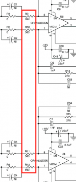
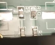
And now for some smd soldering... "input resistors", I trust these would be the four: R9..R12!?
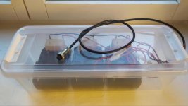
Battery-box (almost) finsihed 🙂 and complete with a power on switch.
//
Battery-box (almost) finsihed 🙂 and complete with a power on switch.
//
Attachments
Last edited:
Indeed, it's those four.
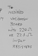
Is the cable between the microphone part and the evaluation module short enough to be directly driven by the op-amps that buffer the microphone signal? Otherwise you may still need 22 ohm or so series resistors between the op-amps and the cable.
Is the cable between the microphone part and the evaluation module short enough to be directly driven by the op-amps that buffer the microphone signal? Otherwise you may still need 22 ohm or so series resistors between the op-amps and the cable.
Thanks!
The cables will be something like 2 meters as the "EVM box" became so large that I can not house it up on the stand as I had hoped for. Will this length require 22 ohms at the output side do you think?
//
The cables will be something like 2 meters as the "EVM box" became so large that I can not house it up on the stand as I had hoped for. Will this length require 22 ohms at the output side do you think?
//
OK!
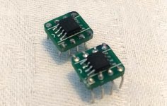
Managed to remove 560 ohm and replace with 221. They where 1/8 instead of 1/10W and 0,05 instead of 0,1%. But you never know with these little buggers. Good these where the bigger ones 🙂
Please inspect my work. I have 2 extra if I was to fail... tried to do quick soldering...
//
Managed to remove 560 ohm and replace with 221. They where 1/8 instead of 1/10W and 0,05 instead of 0,1%. But you never know with these little buggers. Good these where the bigger ones 🙂
Please inspect my work. I have 2 extra if I was to fail... tried to do quick soldering...
//
Attachments
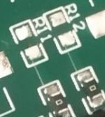
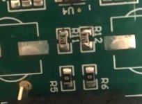
You didn't lift any pads or destroy the PCB. Good! The resistors look like they are well enough connected.
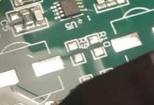
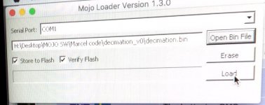
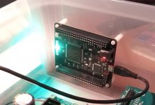
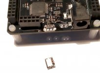
Decided to load the .bin to the FPGA board. Its started good. I managed to set up Wine on my Mac with some help from youtube re how to get a COM1 visible. At USB connection the board lit up and did some LED dancing. But as I hit "Load" on the Mojo Loader app, the board just went black. I waited 1 minute - no progress bar action in the app. Disconnected the USB and as I reconnected the cable, the smd USB connecter came off. Sigh. Well, one get what one pay for... The boards don't look to good - not clean with a lot of soldering residues etc. One can alos see that the two cups for the tags to secure the connector to the board don't seem to be soldered...
I have contacted the seller...
It seemed like the once I started loading the bin file, there was an electrical failure. Maybe the extra current draw broke something? I did not feed the 5V power terminal on the board - maybe one have to do that...? Noo....?
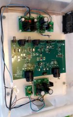
I almost finished the cabling in the ADC-box. All stabs give the correct voltage but I haven't connected the boards.
//
I have contacted the seller...
It seemed like the once I started loading the bin file, there was an electrical failure. Maybe the extra current draw broke something? I did not feed the 5V power terminal on the board - maybe one have to do that...? Noo....?
I almost finished the cabling in the ADC-box. All stabs give the correct voltage but I haven't connected the boards.
//
Attachments
Last edited:
Marcel, may I ask you if you could open the bag and check if it looks like the USB connector has been hand soldered? Mine had clear marks of hot iron on the plastic part of the front/entrance close to the where the connector meet the PCB. And by all means load the bin file if you have the time and will...
//
//
Thanks! I think you should be able to see if the support pins are soldered. If not, proceed cautious 😉
//
//
The upgrade form v2 to v3 was a through hole USB connector. These where not named Mojo or specified as v3. Some are at ebay but from pictures it's hard to tell if they have a TH component - like Mojo V3 FPGA Development Board Module Spartan 6 XC6SLX9 FPGA for Arduino US | eBay which I now ordered. I will try to get the money back on the broken one.
Difference between Mojo V3 and V2? - Embedded Micro
Why did someone do manual work on the usb connector? Hmm...
//
Difference between Mojo V3 and V2? - Embedded Micro
Why did someone do manual work on the usb connector? Hmm...
//
Maybe a board starts with USB only but once the FPGA is engaged its to much current for the USB only to manage? I could not find any manual or tutorial on how to actual connect and program this kind of board. Only a lot of software stuff...
I got a refund.
//
I got a refund.
//
There are holes in the PCB, but the mounting pins of the USB connector don't quite extend to the backside. The microcontroller is an Atmel MEGA32U4. There is no "Mojo vsomething" printed anywhere.
The Mojo V3 that you see here
Updating the Mojo | Alchitry
also has holes for the USB connector, but no pins sticking out from the backside.
It looks to me like a clone of a Mojo V3. The PCB design looks the same as on Updating the Mojo | Alchitry , but without the logo and with a different finish.
The Mojo V3 that you see here
Updating the Mojo | Alchitry
also has holes for the USB connector, but no pins sticking out from the backside.
It looks to me like a clone of a Mojo V3. The PCB design looks the same as on Updating the Mojo | Alchitry , but without the logo and with a different finish.
Yes - this is my insight also.
Does it look dirty and as someone has done some hand soldering job on the connector?
//
Does it look dirty and as someone has done some hand soldering job on the connector?
//
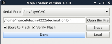
I've done apt-get install openjdk-7-jre-headless and unpacked Mojo loader version 1.3.0 on a computer running Debian Linux and that seems to work; at least Mojo loader claims to have successfully flashed and verified the .bin file.
I can't check at the moment whether the FPGA module does anything useful. The green LEDs turned off while the red LED is still lit, so at least its behaviour changed.
I can't check at the moment whether the FPGA module does anything useful. The green LEDs turned off while the red LED is still lit, so at least its behaviour changed.
Attachments
Does it look dirty and as someone has done some hand soldering job on the connector?
//
I see some flux residues around JP2, but not around the USB connector.
Regarding supply currents of the circuit of post #132 with two 22 ohm series resistors added to it and loaded by the modified evaluation module with 220 ohm input resistors:
EM273: about 0.5 mA
78L08A: max. 6 mA
LED + diode: about 2 mA
OPA1612: max. 4.5 mA per channel quiescent current, so 9 mA total
Peak signal current: about 2.5 V/(1.1 * 303.66 ohm) ~= 7.5 mA
Grand total 16.5 mA for the -15 V and 25 mA for the +15 V.
EM273: about 0.5 mA
78L08A: max. 6 mA
LED + diode: about 2 mA
OPA1612: max. 4.5 mA per channel quiescent current, so 9 mA total
Peak signal current: about 2.5 V/(1.1 * 303.66 ohm) ~= 7.5 mA
Grand total 16.5 mA for the -15 V and 25 mA for the +15 V.
- Home
- Source & Line
- Digital Line Level
- Fixed gain field recorder?