So no worries that there will be 2 boiled eggs after an hour of recording 😉 - good!
1/2 a watt per sphere if I have had the bliss to record: Opeth - The Leper Affinity [In Live Concert at The Royal Albert Hall] HD - YouTube
//
1/2 a watt per sphere if I have had the bliss to record: Opeth - The Leper Affinity [In Live Concert at The Royal Albert Hall] HD - YouTube
//
I forgot about 1.5 mA peak signal current through the bootstrapping resistors, but that won't change the conclusion.
Regarding the FPGA module, I can't do any functional checks until the end of next week.
Regarding the FPGA module, I can't do any functional checks until the end of next week.
Last edited:
Perfectomento!
I will not have another Mojo until a couple of weeks. But you can wait with any tests until I have failed 🙂
Got the 8v stabs today so now I will focus on the spheres.
//
I will not have another Mojo until a couple of weeks. But you can wait with any tests until I have failed 🙂
Got the 8v stabs today so now I will focus on the spheres.
//

Because I had already drawn a 47 uF electrolytic capacitor at the input of the 78L08A, which I assumed to be placed close to the op-amp.
Or if I have really short leads (mm) between LT stabs and opamp power in, I can leave out the caps... or have small value ones - i.e. the 0,1 uF only?
This would be advantageous space wise 🙂
//
This would be advantageous space wise 🙂
//
Sorry, I misinterpreted what you wrote. The regulator PCBs will very probably have a big capacitor across their outputs for reasons of stability, so if you can place their outputs within a few millimetres from the op-amp, you need neither the 47 uF nor the 100 nF.
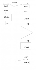
How do you connect the +/- 15 V supplies of the PCM4222EVM?
How do you connect the +/- 15 V supplies of the PCM4222EVM?
Last edited:
OK - thanks!! Yes, I was a bit puzzled 🙂 Thats really good! Saves a lot of space and tricky soldering... great!
So then remains only 2 pcs of 47uF - the one at the + on the second OPA inlet & the bootstrap 47uF - right!?
//
So then remains only 2 pcs of 47uF - the one at the + on the second OPA inlet & the bootstrap 47uF - right!?
//
I'm losing track... Can you make a sketch of what goes where or link to such a sketch if it already exists and is up to date?
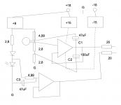
Yes, it's there to get rid of the noise of the LED and diode and improve the PSRR. I had the bottom 4.99 kohm resistor connected to the other side of the diode, but you have to experiment with that anyway.
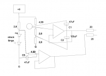
I see now that the ground of the microphone capsule isn't drawn.
The connections from the OPA to the nearest decoupling capacitors (that is, those on the regulator boards) need to be short enough not to cause instability. That is, the loop from OPA1612 pin 8 via the decoupling capacitor of the positive regulator, through ground, via the decoupling capacitor of the negative regulator to OPA1612 pin 4 has to be small enough not to have so much inductance that the OPA1612 starts oscillating or gets quite close to oscillating. Unfortunately it isn't specified anywhere how much inductance is still acceptable. I know from experience with other audio op-amps on perfboard that a few centimetres usually doesn't cause trouble, but the faster the op-amp, the less wire you need to get trouble. Placing 100 nF capacitors with a small physical size right next to the OPA1612, as recommended in its datasheet, is a way to avoid the whole issue, but unfortunately you are short on board space.
For minimum sensitivity to hum, you have to put a shield (Faraday's cage) around the whole thing and minimize these loop areas:
+ input of the bottom op-amp, C3, ground wire to the microphone capsule, output of the microphone capsule, + input of the upper op-amp
op-amp outputs, 20 ohm (or 22 ohm) resistors, signal cable to the evaluation module.
The cable should be a shielded and twisted cable, like any professional microphone cable. As always, the shield protects against low-frequency electric fields and high-frequency electric and magnetic fields, the twisting against low-frequency magnetic fields such as hum fields.
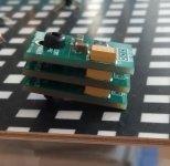
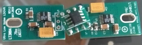
If I stand the regulators up (they will be mounted on the other side of the board) about these lengths should be achievable. I think I need to chop off the top part of the regulators to fit them but as I only use 10% of their capacity, it should be OK thermal wise I think.
//
//
Attachments
Last edited:
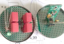
Potential basic layout. See this as if you saw both sides on the same board. I might be able to not have to go via the board for the power feed - just solder some pins for physical mounting/stability and then hardwire p-p. 3 resistors is lacking on the "component side" else it is complete. The cable will be like taking in a full grown Pine for Christmas tree 🙂... it will need some physical relief in order to not wiggle its connections points... tricky... and at the same time one need to be able to dismantle the whole thing... will take some thinking... slowly slowly... ;-D
//
//
Attachments
- Home
- Source & Line
- Digital Line Level
- Fixed gain field recorder?