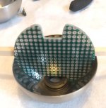
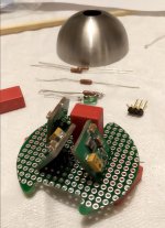
Not much happened... but I managed to decapitate the regulators in order fo them to fit in the spheres. also looking into cabling to the mics... Got some toslink transmitters which I hope can substitute one of the coax outputs on the EVM board with teh aid of some 3,3v and a cap... 5PCS NOS Toshiba TOTX141L TOTX141 TRANSMITTER MODULE FIBER OPTIC | eBay
//
//
Attachments

I gather that's for tests without the FPGA board and the Ian Canada board, as the Ian Canada board already has an optical output.
I expect you will have to AC couple (100 nF should do) one of the PCM4222 evaluation module S/PDIF / 75 ohm AES3 outputs to the input and use two resistors to bias it somewhere around 1.5 V. When you use 150 ohm to ground and 180 ohm to the 3.3 V, you will have almost the right termination impedance for S/PDIF. The PCM4222 evaluation module has no 3.3 V LVCMOS S/PDIF outputs for directly driving an optical transmitter, as far as I can tell from looking at the schematic.
I expect you will have to AC couple (100 nF should do) one of the PCM4222 evaluation module S/PDIF / 75 ohm AES3 outputs to the input and use two resistors to bias it somewhere around 1.5 V. When you use 150 ohm to ground and 180 ohm to the 3.3 V, you will have almost the right termination impedance for S/PDIF. The PCM4222 evaluation module has no 3.3 V LVCMOS S/PDIF outputs for directly driving an optical transmitter, as far as I can tell from looking at the schematic.
Okey - I ment to ask about this actually. Yes, it was for the event that I wanted to try the EVM by itself. Now, as things has developed, I'm not so keen in that but will instead aim the resources to get this working with the hopefully soon arriving new FPGA board. It would have been better with a smaller board for i2s->toslink but when I searched for one I was not so keen on anything I was finding... so Ian it will be...
//
//
Ians clock board is nice and high quality. But its quite large. I recall that I have an other board that might be able to do the job...
WM8805 I2S to SPDIF Coaxial, CD Player Adds Coaxial Output Support 44.1K 192K V4|Tool Parts| - AliExpress
I suppose I have a Model 1 type board which has a MCK input along with the other 4 i2s signals...?
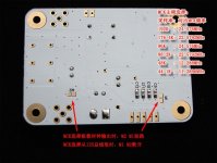
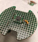
TX141L did not fit on the board... where and how to connect it?
TX141L:
Supply Voltage VCC2.7 3.0 3.6 V
High−Level Input Voltage VIH2.1 ― VCCV
Low−Level Input Voltage VIL0 ― 0.9 V
No real manual for that board... and my chinese is limited. Maybe I have to ask for some translation help on the forum...
//
WM8805 I2S to SPDIF Coaxial, CD Player Adds Coaxial Output Support 44.1K 192K V4|Tool Parts| - AliExpress
I suppose I have a Model 1 type board which has a MCK input along with the other 4 i2s signals...?
TX141L did not fit on the board... where and how to connect it?
TX141L:
Supply Voltage VCC2.7 3.0 3.6 V
High−Level Input Voltage VIH2.1 ― VCCV
Low−Level Input Voltage VIL0 ― 0.9 V
No real manual for that board... and my chinese is limited. Maybe I have to ask for some translation help on the forum...
//
Attachments
Not sure why you are calling that a clock board?
From the pics it looks more like a SPDIF transmitter board.
From the pics it looks more like a SPDIF transmitter board.
Thats correct - my bad - its the IO board I'm thinking to use. Other thoughts ended up on the keyboard as I'm actually contemplating also using an Ian clock board in there to extract an external clock ref to the EVM board 🙂
//
//
Why not use an internal crystal clock?
Maybe better to do that, and then use ASRC or FIFO on the SPDIF receiving end to synchronize with a local crystal there?
Maybe better to do that, and then use ASRC or FIFO on the SPDIF receiving end to synchronize with a local crystal there?
Why would you want to use an ASRC, or an external clock? It's an ADC, so you don't have the issue that you have in a DAC with S/PDIF, Toslink or AES3 input, that you want a clean clock for the converter but need to slave to whatever comes in.
You mean: Why not use the internal crystal clock? The toslink receiver is a computer for storage so no ASRC is wanted but rather avoided. The EVM has an onboard clock of ordinary quality but also a connector for an external clock - hence the Ian clock board for which I have a better osc. But I'm not sure the quality from an external source is carried over to beat a smd clock mounted on the board. This is for future evaluation perhaps.
//
//
I have an Ian clock board, the one designed for use with McFIFO. Wouldn't use that one myself, not as-is anyway. Clocking on FIFO_Pi Ver. 3 has received more recent clocking design developments.
So you want to use either the internal clock or a higher-performance external clock and no ASRC. Makes sense.
Yes!
Mk4 - your last post is confusing and make no sense to me. I own none of the products you mention and I have no plan of getting them.
//
Mk4 - your last post is confusing and make no sense to me. I own none of the products you mention and I have no plan of getting them.
//
You mentioned an "Ian clock board." If you have a link for the one you mean, I will see if its the same one I was thinking of.
Ians clock board is nice and high quality. But its quite large. I recall that I have an other board that might be able to do the job...
WM8805 I2S to SPDIF Coaxial, CD Player Adds Coaxial Output Support 44.1K 192K V4|Tool Parts| - AliExpress
I suppose I have a Model 1 type board which has a MCK input along with the other 4 i2s signals...?
TX141L did not fit on the board... where and how to connect it?
TX141L:
Supply Voltage VCC2.7 3.0 3.6 V
High−Level Input Voltage VIH2.1 ― VCCV
Low−Level Input Voltage VIL0 ― 0.9 V
No real manual for that board... and my chinese is limited. Maybe I have to ask for some translation help on the forum...
//
i wonder what master clock frequency it requires at 88.2 kHz sample rate. Apparently the WM8805 has a default master clock of 256 fs, see https://statics.cirrus.com/pubs/proDatasheet/WM8805_v4.5.pdf , while the evaluation module outputs 128 times 88.2 kHz via J6 pin 1. If you can find a way to get the undivided 22.5792 MHz out of the evaluation module, then you have 256 times 88.2 kHz.
Your suport warms my heart - thanks again for all your help Marcel - really appreciate it 🙂
Maybe stick to the Ian solution to begin with... this board might just create trouble.
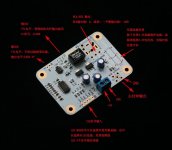
But while I'm at it... the screen says s/pdif output and has 3 pins: "+", "-" and "G" (which is strange as s/pdif is "single end")
The TX141L has:
"G", "signal" and +3V.
How do one combine these I wonder...
G:G
+:signal
don't use board "-".
//
Maybe stick to the Ian solution to begin with... this board might just create trouble.
But while I'm at it... the screen says s/pdif output and has 3 pins: "+", "-" and "G" (which is strange as s/pdif is "single end")
The TX141L has:
"G", "signal" and +3V.
How do one combine these I wonder...
G:G
+:signal
don't use board "-".
//
It says RCA/AES, so it could be that the signal is between + and -. I guess you need help from someone who is good at Chinese.
You need a trick with a capacitor and two resistors and a bit of luck to couple a real (rather than a TTL or LVCMOS) S/PDIF signal into an optical transmitter, but we discussed that before.
You need a trick with a capacitor and two resistors and a bit of luck to couple a real (rather than a TTL or LVCMOS) S/PDIF signal into an optical transmitter, but we discussed that before.
It's hard. 🙂 ... geting both miffed and psyched that I have such a struggle to build this simple schema. It is double side and a bit of 3D but still.. I gave up on trying to do a drawing and rather sat the OP amp and arranged the voltage feed to it in the best way acc to Marcels recommendations. The SOIC adapter twists the OP amp 90 deg and there is a "long" trace to leg 4 and 8 to the pins. I could save 3-4 mm by rotating the regulators and do short cuts from the regulator pin straight up to the OP amp smd leg (blue instead of red) - worth it?
I'm tired. More tomorrow...
//
I'm tired. More tomorrow...
//
Attachments

Last edited:
- Home
- Source & Line
- Digital Line Level
- Fixed gain field recorder?