Thank you for your explanation. I'm mainly an end-user more than a DIY-er, so the thought of an integrated FIFO Lite with an optical output would had been a dream.
My current FiFoPi Q3 is dedicated for portable use, so I am at a crossroads on what's next.
I'm not sure if I want to go with another FiFoPi Q3 plus a TWTMC finished board for the desktop quite yet. The FIFO Lite would of been a nice alternative.
I'm guessing no USB output on the FIFO Lite? I'm now using USB optical solutions and maybe Thunderbolt 3 optical for my desktop build, so I'm open to using USB again.
Found answer:
I guess I have to horse blinder the FiFoPi Q3 plus a TWTMC finished board solution.I wouldn't use the PC as the source so the USB is not practicable.
Last edited:
The FIFO Lite has 4 x I2S input so you should install a USB to I2S adapter to use the PC.
The output is I2S, PCM and custom to feed the DAC Lite, the AD5791 and the upgraded Soekris DAM1021.
The outputs are via copper only because optical communication adds a lot of jitter vanishing the performance of the FIFO.
The output is I2S, PCM and custom to feed the DAC Lite, the AD5791 and the upgraded Soekris DAM1021.
The outputs are via copper only because optical communication adds a lot of jitter vanishing the performance of the FIFO.
I was initially planning to use a USB to I2S adapter for the Ian solution so that's straightforward.
I'll check if it's possible to use a unreleased Ian I2S adapter to Ian TransportPi (optical output) via GPIO. Or if there's a I2S to USB solution.
Thanks. I'm burnt out with RPi, so want to explore 12V PC solutions.
I'll check if it's possible to use a unreleased Ian I2S adapter to Ian TransportPi (optical output) via GPIO. Or if there's a I2S to USB solution.
Thanks. I'm burnt out with RPi, so want to explore 12V PC solutions.
For an extremely inexpensive optical to i2s interface supporting up to 192Khz these interfaces from Aliexpress do the trick by bypassing the DAC.
Since the cs8416 is so basic I dont know how necessary an isolator+ isolated supply would be between it and the FIFO.
Since the cs8416 is so basic I dont know how necessary an isolator+ isolated supply would be between it and the FIFO.
Hi All!
Dear Andrea, I want to use the I2S reclocker to regenerate the I2S stream coming from the CS8414 to the TDA1541(A) in my DAC. The idea is to use the three jumpers available in the DAC board.

Would it be possible to do like this?

My doubt is about the I2S format. The TDA1541 I2S input format should be OB/TWC so, would the I2S reclocker accept this format on its input?
Thank you!")
Dear Andrea, I want to use the I2S reclocker to regenerate the I2S stream coming from the CS8414 to the TDA1541(A) in my DAC. The idea is to use the three jumpers available in the DAC board.
Would it be possible to do like this?
My doubt is about the I2S format. The TDA1541 I2S input format should be OB/TWC so, would the I2S reclocker accept this format on its input?
Thank you!
For an extremely inexpensive optical to i2s interface supporting up to 192Khz these interfaces from Aliexpress do the trick by bypassing the DAC.
Since the cs8416 is so basic I dont know how necessary an isolator+ isolated supply would be between it and the FIFO.
Hi @lasercut
I don't know if this was directed towards my previous post.
If it was, thanks anyways but I gave up on a 12V source.
For my DAC, optimal reference is toslink <= 192 so sticking with RPi I2S w/ TransportPi OPT OUT.
I don't upsample ATM, but I'm saving the 12V source for > 192. There are loads that use PGGB software remastering/upsampling so if I get into that then I'll revisit a 12V source. I only consider USB again because I now have a USB optical solution and Andrea offers USB capable clocks. Otherwise, I had completely given up on USB + 12V source.
A toast to PGGB, a heady brew of math and magic - Software - Audiophile Style
I'm perfectly content for now without upsampling. I separated projects because it's not optimal to combine.
If the FiFo Lite transformed to toslink or USB, then I would consider but it's targeted towards DIY DACs so I'll likely pickup another FiFoPi Q3 w/ OPT OUT.
Last edited:
Oh, so sort of like the function of the ReceiverPi. You can make it accept an SPDIF output and ReClock?
But then I have the problem of transforming a toslink output...
Great idea. Wish I could of made this work but I don't think I can get toslink OUT, so have to move on and back to a Q3.
But then I have the problem of transforming a toslink output...
Great idea. Wish I could of made this work but I don't think I can get toslink OUT, so have to move on and back to a Q3.
Work in progress
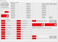
We are testing the firmware and the software of the FIFO Lite, the design is almost ready to be tested with some DACs.
I'm now working on the Windows software to be used to manage the board settings.
The board will come with the firmware for the micro already installed, while the firmware for the FPGA will be loaded by the user via USB using the Windows application.
There was a default for each setting, but the specific settings for the DAC to be drived have to be configured according to the DAC board by the Windows application.
There will be a manual to manage the settings and the configuration for the most common DAC will be preloaded.
This way one can simply select the DAC from a combo box and all the needed parameters will be loaded automatically.
I attach a picture of the Windows test application we are using to manage the settings.
The final application will be different but above all more user friendly.
Attachments
We are testing the firmware and the software of the FIFO Lite, the design is almost ready to be tested with some DACs.
I'm now working on the Windows software to be used to manage the board settings.
The board will come with the firmware for the micro already installed, while the firmware for the FPGA will be loaded by the user via USB using the Windows application.
There was a default for each setting, but the specific settings for the DAC to be drived have to be configured according to the DAC board by the Windows application.
There will be a manual to manage the settings and the configuration for the most common DAC will be preloaded.
This way one can simply select the DAC from a combo box and all the needed parameters will be loaded automatically.
I attach a picture of the Windows test application we are using to manage the settings.
The final application will be different but above all more user friendly.
... nice !
very nice indeed
Hi Eduard,
it's a little different, let me list some differences:
- 4 x selectable I2S input
- output format compatible with almost all modern and old DACs
- custom output format for TDA1541A (offset binary), our DAC Lite, Soekris DAM1021 upgrade, AD5791
- selectable stopped or continuous clock
- 8 x selectable dither depth separately for each source (used in case of data truncation, eg 24 to 16 bit for the TDA1541A)
- 8 x selectable buffer depth separately for each source, from 65kb to 8Mb
- digital DAC calibration to reach the best precision, DAC Lite and maybe other DACs
- all settings can be configured one time by USB connection to the Windows application
- user interface to manage some function on the fly like source selection, dither, enable/disable DAC calibration and so on
- T-switch configuration relais to select the sample rate family instead of multiplexers
- MCK and LRCK optical isolated from the FPGA and the micro to avoid interferences (BCK too with the OIR reclocker board)
- SMA connectors for external clocks
- micro controller in standby during listening (no RF interference at all)
- LRCK directly from the MCK (optical isolation) instead of from the FPGA
- very low phase noise outputs (MCK, LRCK, BCK with OIR board), plots published
Maybe I forgot some.
Andrea
Hi Andrea, will there be the possibility of „right justified“ as output format?
Thanks!
Greetings
Oli
What DAC you would you like to drive?
- Home
- Source & Line
- Digital Line Level
- The Well synchronized asynchronous FIFO buffer - Slaved I2S reclocker