On the other hand, a high order DSM might make the sound too thin, as if too much micro details pop up and make the whole thing sound artificial.
That description of too much micro detail could suffice as a perceptual description of some types of low level distortion. Never found it to be due to noise exactly. Of course, distortion doesn't have to be produced inside the dac itself. RF leakage can cause distortion to increase in subsequent analog processing, as one possible issue.
Are the design choices you make based on listening preferences solely or partly or not at all?
My 1bitDSM isn't for measurement purposes but for listening; for music. My decision must base on hearing experience. But it's impossible to have a listening test to decide the architecture (DSM order, OSR, and hardware) because I haven't yet fixed up my DAC. What I can convince in my experience is that a low noise floor without fluctuation and excellent IMD are important. THD is less critical because real music has many spectra where single tone performance(THD) is meaningless. 1bitDSM is the best way to achieve low IMD because it's free from lineality in the conversion process. I'm sure discrete multi-bit DSM can't outperform 1bitDSM in IMD. So, my essential strategy to design 1bitDSM is to have a low noise floor, where no fluctuation is already guaranteed. That's the reason I chose the 4th order DSM and 128OSR.
I'm looking forward to having a comparison between low order DSM and high order one when I have fixed the DAC. It's easy to configure FPGA to have high order DSM since I already have configuration data of the 8th order.
I'm now a little bit at a loss as to which way is the best for 1bitDSM. I have decided to employ analog FIR architecture to achieve an excellent noise floor(more than 120dB). It's probably possible to reach 120dB if you have 48 taps. But 1bit DSM is the West where the wild plain is intact; you can have many ways that nobody ever tries. There may exist a better method than 48 taps analog FIR. Existing 1bitDSM(Chord) probably isn't analog FIR but has excellent performance. I don't know "pulse array" that Chord claims. I'm still under construction about another architecture while struggling with real PCB having analog FIR.
P.S. what Tek is that?
MDO3102
Last edited:
Hi all - good to see that this thread is fine and alive ... following on the side very interested the progress of xx3stksm's designs ...
@mterbekke:
In my experience there's one aspect of frequency shifting that I rarely see discussed: And that is that when one changes the sampling frequency the silicon's decoupling capacitors may "significantly" change their characteristics. Thus a typical 100 nF C0G decoupling capacitor may have a ~10 mohm impedance at 12.3 MHz (192 kHz sampling frequency master clock) whereas at 6.144 MHz it may be around 200 mohms. This is a 26 dB difference ... And then there is the challenge of this being square wave signals so that the harmonics on the PSU decoupling are no way easy to deal with...
I haven't yet had the time to deal with this in detail but some time ago I listened to different 100 nF 1206 C0G quality capacitors by substituting them into a very small custom made socket. They sounded quite audibly different. And particularly in the upper frequency range where whiteness vs. roundness vs. tonal fullness were some of the audible differences.
So IMHO one of the shortcomings in today's digital is the many sample frequencies. Personally, I would prefer one (high - e.g. 1.536 MHz) sampling frequency and then work from there ... But one may always dream, right ;-)
Anyway this just came up ... Have a good evening, day, or morning wherever in the world this may fit your time of day")
Jesper
@mterbekke:
On the other hand, a high order DSM might make the sound too thin, as if too much micro details pop up and make the whole thing sound artificial.
In my experience there's one aspect of frequency shifting that I rarely see discussed: And that is that when one changes the sampling frequency the silicon's decoupling capacitors may "significantly" change their characteristics. Thus a typical 100 nF C0G decoupling capacitor may have a ~10 mohm impedance at 12.3 MHz (192 kHz sampling frequency master clock) whereas at 6.144 MHz it may be around 200 mohms. This is a 26 dB difference ... And then there is the challenge of this being square wave signals so that the harmonics on the PSU decoupling are no way easy to deal with...
I haven't yet had the time to deal with this in detail but some time ago I listened to different 100 nF 1206 C0G quality capacitors by substituting them into a very small custom made socket. They sounded quite audibly different. And particularly in the upper frequency range where whiteness vs. roundness vs. tonal fullness were some of the audible differences.
So IMHO one of the shortcomings in today's digital is the many sample frequencies. Personally, I would prefer one (high - e.g. 1.536 MHz) sampling frequency and then work from there ... But one may always dream, right ;-)
Anyway this just came up ... Have a good evening, day, or morning wherever in the world this may fit your time of day
Jesper
That description of too much micro detail could suffice as a perceptual description of some types of low level distortion. Never found it to be due to noise exactly. Of course, distortion doesn't have to be produced inside the dac itself. RF leakage can cause distortion to increase in subsequent analog processing, as one possible issue.
Exactly. Can't really think of any other known mechanism (to me) that does this.
The faster the logic, the less it's a problem afaik and indeed: I also don't perceive that the order of the LPF influences it much, if at all.
So to me, as of now, RF leakage is not a major factor in this, logic speed is.
Has anybody here mastered the art of RTZ encoding on dsd?
I suspect that the faster logic gives less rise to some sort of modulation of the average noise level (that may be under, or within, or even above) that's hard to grasp with steady state signals, so these might be solved by using RTZ encoding.
Still not sure.
Any thoughts on that would be more than welcome!
The faster the logic, the less it's a problem afaik and indeed: I also don't perceive that the order of the LPF influences it much, if at all.
Parasitic inductance interacting with LP filter caps, and ground conducted noise (including antenna effects), etc. are not uncommon issues. Often such effects are not apparent from looking at schematics, nor apparent to the untrained/inexperienced eye looking at physical circuits. We humans tend to think of a problem in terms of the facts we know about as though that is all there is.
Personally, I have been surprised a few times by finding evidence of RF induced audio distortion that nobody thinks should be there. 'Out of sight, out of mind,' just part of having a human brain.
Last edited:
My 1bitDSM isn't for measurement purposes but for listening; for music. My decision must base on hearing experience. But it's impossible to have a listening test to decide the architecture (DSM order, OSR, and hardware) because I haven't yet fixed up my DAC. What I can convince in my experience is that a low noise floor without fluctuation and excellent IMD are important. THD is less critical because real music has many spectra where single tone performance(THD) is meaningless. 1bitDSM is the best way to achieve low IMD because it's free from lineality in the conversion process. I'm sure discrete multi-bit DSM can't outperform 1bitDSM in IMD. So, my essential strategy to design 1bitDSM is to have a low noise floor, where no fluctuation is already guaranteed. That's the reason I chose the 4th order DSM and 128OSR.
I'm looking forward to having a comparison between low order DSM and high order one when I have fixed the DAC. It's easy to configure FPGA to have high order DSM since I already have configuration data of the 8th order.
I'm now a little bit at a loss as to which way is the best for 1bitDSM. I have decided to employ analog FIR architecture to achieve an excellent noise floor(more than 120dB). It's probably possible to reach 120dB if you have 48 taps. But 1bit DSM is the West where the wild plain is intact; you can have many ways that nobody ever tries. There may exist a better method than 48 taps analog FIR. Existing 1bitDSM(Chord) probably isn't analog FIR but has excellent performance. I don't know "pulse array" that Chord claims. I'm still under construction about another architecture while struggling with real PCB having analog FIR.
MDO3102
I understand and agree about noise modulation, fluctuation, noise floor and thd.
What I was getting at is that e.g. a low noise floor ultimately brings the xx-taps to one's attention, which may skew the software (a certain OSR and order of DSM) in a different direction than had you chosen on e.g. 110 dB SN / THD (chosen a different hardware implementation).
I am, as of yet, not shure about the correlation of measured goals and perceived SQ: maybe e.g. 106dB of the cleanest IMD and THD is enough, maybe even best because all things else can be kept more simple.
This is by no means meant as a way to criticize what you're doing an how you're doing it, it's just me thinking out loud, pondering about what we as engineers do what we do: we set goals and have to crack some hard nuts to get where we want to get.
And there's one more good thing: by setting this high goal: it's always possible to strip your dac to less taps and see how SQ scales.
Would you be interested to share or sale the design files and software to the diy community once you're ready with prototyping, or do you have bigger / more commercial plans? This question might be answered many months from now, or not at all, I'm just curious ;-)
Tek looks great, does it perform great as well?
Hi all - good to see that this thread is fine and alive ... following on the side very interested the progress of xx3stksm's designs ...
@mterbekke:
In my experience there's one aspect of frequency shifting that I rarely see discussed: And that is that when one changes the sampling frequency the silicon's decoupling capacitors may "significantly" change their characteristics. Thus a typical 100 nF C0G decoupling capacitor may have a ~10 mohm impedance at 12.3 MHz (192 kHz sampling frequency master clock) whereas at 6.144 MHz it may be around 200 mohms. This is a 26 dB difference ... And then there is the challenge of this being square wave signals so that the harmonics on the PSU decoupling are no way easy to deal with...
I haven't yet had the time to deal with this in detail but some time ago I listened to different 100 nF 1206 C0G quality capacitors by substituting them into a very small custom made socket. They sounded quite audibly different. And particularly in the upper frequency range where whiteness vs. roundness vs. tonal fullness were some of the audible differences.
So IMHO one of the shortcomings in today's digital is the many sample frequencies. Personally, I would prefer one (high - e.g. 1.536 MHz) sampling frequency and then work from there ... But one may always dream, right ;-)
Anyway this just came up ... Have a good evening, day, or morning wherever in the world this may fit your time of day
Jesper
Hmm
You might be right.
Either way: I always play at dsd512 and at a fixed family (44 or 48), so nothing to gain from that perspective.
Nonetheless, fast rise times as well as fairly high frequencies and LF is a mixed bag of cap size, cap values, path lengths, ground bounce, reflections etc etc.
Even without those I'd dare to say that comparable caps could sound different, even when given the exact same load.
Parasitic inductance interacting with LP filter caps, and ground conducted noise (including antenna effects), etc. are not uncommon issues. Often such effects are not apparent from looking at schematics, nor apparent to the untrained/inexperienced eye looking at physical circuits. We humans tend to think of a problem in terms of the facts we know about as though that is all there is.
Personally, I have been surprised a few times by finding evidence of RF induced audio distortion that nobody thinks should be there. 'Out of sight, out of mind,' just part of having a human brain.
Oh by no means do I think I have a say in this. I'm sure I also have overlooked many rf problems and they might have or not caused problems further up on the road.
Usually when a certain way of doing things (layout, used brand/type/size of caps etc) work well, you tend to keep it that way: set and forget. Out of sight, out of mind indeed!
Yet one would also intuitively accept that faster edge rates would generate a stronger response to changed OSR rates (dsd64 to dsd512) and DSM settings if leakage etc is a problem. There are definitely changes but the edge rates (more specific: exact logic family) make a bigger difference (better sq).
The only way out of this reasoning is that the edge rate enhancement to me is achieved by changing from cmos to cml logic. That's a low ground bounce as well as true differential family.
So if there's significant rf problems upstream, I suspect looking at the kind of rf problems that is specific to the families that don't work that way.
By e.g. leakage, do you "just" measure the rf components at the lf output or are there some cool tricks and tips tou might want to share that we might specifically look for?
What comes to my mind is the obvious like the clock frequencies at the lf output, but that's all for starters right?!
So IMHO one of the shortcomings in today's digital is the many sample frequencies. Personally, I would prefer one (high - e.g. 1.536 MHz) sampling frequency and then work from there ... But one may always dream, right ;-)
Anyway this just came up ... Have a good evening, day, or morning wherever in the world this may fit your time of day
Jesper
You could run the sigma-delta at 112.896 MHz, that's the smallest common multiple of all the usual sample rates including DSD up to DSD512 (assuming DSD is always at a multiple of 44.1 kHz). Or use non-integer sample rate conversion, of course.
What I was getting at is that e.g. a low noise floor ultimately brings the xx-taps to one's attention, which may skew the software (a certain OSR and order of DSM) in a different direction than had you chosen on e.g. 110 dB SN / THD (chosen a different hardware implementation).
My system has a high-efficiency horn driver(113dB) for mid-range. The DAC for mid-range is completely different from the low-range because the efficiency, average amplitude of mid-range, and equal-loudness-level contours bring you considerable degradation of SNR. Rough estimation is 15dB(efficiency)+20dB(amplitude)+10dB(loudness)=45dB. My current DAC has 110dB SNR(3bit DSM), but the actual SNR can be 110-45=65dB. When I modified 3bitDSM into 1bitDSM, I couldn't have the same quality as 3bitDSM. You can't get rid of 6dB degradation if your design isn't dedicated to 1bitDSM. My listening test wasn't successful. It sounded rough and lifeless. In my setup, 110dB is probably mandatory because my music file is a classical one, where high SNR is essential.
I would say 120dB may be overkill. My first PCB with FPGA and transistors with 24-taps had excellent results(115dB SNR) more than I expected. Theoretically speaking, 48-taps can have 6dB improvement; eg, 115+6=121dB. That's the reason my goal is more than 120dB. If I take the wrong way, I can't reach the goal. I'm sure 120dB corrects redundant design and brings me the best way. After finishing 48-taps, It's easy to downsize taps from 48 to 36 or 24 for a simple design.
P.S. I have loved Tek since I started my career in the 80's
You could run the sigma-delta at 112.896 MHz, that's the smallest common multiple of all the usual sample rates including DSD up to DSD512 (assuming DSD is always at a multiple of 44.1 kHz).
Hi Marcel, well, yes, that is an option. But to me at least - don't know about you, of course - filtering PSU noise at a 113 MHz base frequency is (much) less simple than at lower frequencies. Not to mention that the phase noise of a clock oscillator operating at these frequencies will increase quite some ... One may of course use a clock multiplier but at these frequencies I would reckon that it will still introduce some additional phase noise.
And won't such fast shifting of a logic also introduce distortion phenomena from the logic itself? E.g. due to different rise and fall times?
Anyway ... "a 1.536 MHz R2R DAC would be simple" ... 1.536 MHz conversion clock derived from a super stable 6.144 MHz crystal - which is then again clock multiplied to the frequency needed to feed the I2S data line .. which is less influenced by not-so-perfect phase noise specs. But then again, maybe a perfect R2R DAC isn't that simple to make ....
... thinking aloud here in the morning ...
Cheers,
Jesper
You could run the sigma-delta at 112.896 MHz, that's the smallest common multiple of all the usual sample rates including DSD up to DSD512 (assuming DSD is always at a multiple of 44.1 kHz). Or use non-integer sample rate conversion, of course.
Why not use 11.2896 × 2 = 22.5792 MHz?
My system has a high-efficiency horn driver(113dB) for mid-range. The DAC for mid-range is completely different from the low-range because the efficiency, average amplitude of mid-range, and equal-loudness-level contours bring you considerable degradation of SNR. Rough estimation is 15dB(efficiency)+20dB(amplitude)+10dB(loudness)=45dB. My current DAC has 110dB SNR(3bit DSM), but the actual SNR can be 110-45=65dB. When I modified 3bitDSM into 1bitDSM, I couldn't have the same quality as 3bitDSM. You can't get rid of 6dB degradation if your design isn't dedicated to 1bitDSM. My listening test wasn't successful. It sounded rough and lifeless. In my setup, 110dB is probably mandatory because my music file is a classical one, where high SNR is essential.
I would say 120dB may be overkill. My first PCB with FPGA and transistors with 24-taps had excellent results(115dB SNR) more than I expected. Theoretically speaking, 48-taps can have 6dB improvement; eg, 115+6=121dB. That's the reason my goal is more than 120dB. If I take the wrong way, I can't reach the goal. I'm sure 120dB corrects redundant design and brings me the best way. After finishing 48-taps, It's easy to downsize taps from 48 to 36 or 24 for a simple design.
P.S. I have loved Tek since I started my career in the 80's
We use the same type of mid-drivers;-)
So you are designing a complete active system, dac's being dedicated to the individual drivers of a multi way setup?
Do you use the same analog amplification for all drivers?
I'm also looking in that direction, for obvious reasons and the plans are to not have analog amplification for the mid/high drivers, just buffers would suffice if there's enough headroom by tweaking the analog output stage of the dac a bit.
Is your oscillation problem maybe partly because all collectors see eachother directly and could this be made less an issue when you'd lead all output currents to the opamp by a series resistor?
Kind of defeats the purpose, using resistors, but low ohmic (10 tot 50) might be enough already.
We use the same type of mid-drivers;-)
So you are designing a complete active system, dac's being dedicated to the individual drivers of a multi way setup?
Do you use the same analog amplification for all drivers?
I'm also looking in that direction, for obvious reasons and the plans are to not have analog amplification for the mid/high drivers, just buffers would suffice if there's enough headroom by tweaking the analog output stage of the dac a bit.
Yes, my current system is a 4-way, where 4 DACs with power stage (10W for low, 3W for mid and high) include digital Xover(1024-taps FIR). The gain arrangement is critical in a multi DAC system because the different efficiency between low and mid is large(usually more than 12dB). The DAC for low is 6Vpp while mid and high are 1.5Vpp, which can roughly cancel the different efficiency. The gain of the power stage for low is almost 6dB, while those for mid and high is 0dB(buffer), as you wrote.
Furthermore, DACs for mid and high are entirely dedicated one for classical music. Their full scale is -12dBFS, not 0dBFS, which improves SNR. My DACs are passive I/V. The DAC for low has 50-ohm resistor while mid and high are 13-ohm, which results in a 12dB decrease of DAC out, including residual noise. But it doesn't mean the improvement of SNR since signal also decreases by 12dB. Then you do logical left shift by two bits in the digital domain, which compensates the decrease of a signal. So, the signal level doesn't change, while residual noise decreases by 12dB. You have an improvement in SNR by 12dB. The trade-off is full scale. More than -12dBFS ends up clipping. But I know classical music never has a large amplitude signal in mid and high. Clipping never occurs. You can only have improved SNR as long as your DAC is free from noise floor fluctuation..
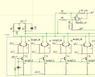
Is your oscillation problem maybe partly because all collectors see eachother directly and could this be made less an issue when you'd lead all output currents to the opamp by a series resistor?
Kind of defeats the purpose, using resistors, but low ohmic (10 tot 50) might be enough already.
I can't understand what you mean. Can I have a pic that clarifies your intention?
By e.g. leakage, do you "just" measure the rf components at the lf output or are there some cool tricks and tips you might want to share that we might specifically look for?
What comes to my mind is the obvious like the clock frequencies at the lf output, but that's all for starters right?!
What I have observed is that low level RF presence in dac outputs which is too little for me to see with a scope can be inferred indirectly. In one case the clue was op amps running at higher temperature than could be accounted for by audio alone. In other cases the clue was that changing audio interconnect wiring length or capacitance between conductors (from dac outputs to I/V or subsequent audio stage) changed low-level audible distortion at the audio output that could not otherwise be accounted for, nor seen on limited bandwidth FFTs. If not clues then I would not have thought there was no problem.
A more direct case was found by tracing RF emissions of a power supply ground using a battery powered short wave radio with external antenna used as a probe. The RF level was too low to see with my scope, but it still caused low level audible distortion in the audio signal that was later corrected by removing the RF at its source. Again, it was necessary for me to become suspicious (and trust my ears) first since routine measurements I am equipped to do did not clearly show there was a problem.
No idea if anecdotal stories as above will be of any use to anyone else. Maybe it will get people thinking for awhile, or not.
Last edited:
It's good for spreading FUD.No idea if anecdotal stories as above will be of any use to anyone else. Maybe it will get people thinking for awhile, or not.
It's good for spreading FUD.
I am missing a smiley or some "wink wink".
Anyway, it is no fud. My colleague builds amps. Some of them oscillate, strongly depending on the length, shape and/or location and or direction of the connected rca cable. It also depends on connected equipment as well as wether wifi equipment is present or not and on sort of signal and level of it.
Either way, the customer complained about changing sound quality per day or whatever time frame.
Once fixed it never came back.
None of this showed up in distortion tests or other standard ways to see if the amp was within spec or not.
It ain't FUD if you don't have your easy to be scared brain on;-)
I can't understand what you mean. Can I have a pic that clarifies your intention?
R1 and R4 serve as common resistors for all transistor collectors, so all taps/transistor collectors share the same R1 and R4.
By a (one) tap you mean a balanced pair of npn transistors with their current source, right?
So right now all positive phase transistors (collectors) all share R1, the negative phase (collectors) all share R4, so all collectors of similar phase are connected to eachother.
I can imagine this causing problems.
It might get less problematic when the collectors won't be connected so directly together. A way of doing this is by having 1 transistor having their own, unique collector resistor. So 1 phase/collector, 1 resistor.
This way you get as many collector resistors as there are collectors.
Getting that voltage out could, for instance, be done by using a serial resistor from the collector to the output. Add as many taps with this structure as you want to that same output point (all with a serial resistor).
Sorry, I'm not at home so can't draw something decent, if it's still not clear I can draw something tomorrow evening (in about 24 hours)
Later back for more, gotta go...
Attachments
Why not use 11.2896 × 2 = 22.5792 MHz?
Because 22.5792 MHz divided by 48 kHz (or 96 kHz or 192 kHz) is not an integer. 28.224 MHz will do if you are not into DSD256 or higher.
Because 22.5792 MHz divided by 48 kHz (or 96 kHz or 192 kHz) is not an integer. 28.224 MHz will do if you are not into DSD256 or higher.
Yes I understand what you meant, but
"(Originally Posted by MarcelvdG
You could run the sigma-delta at 112.896 MHz, that's the smallest common multiple of all the usual sample rates including DSD up to DSD512)(assuming DSD is always at a multiple of 44.1 kHz. Or use non-integer sample rate conversion, of course."
Ah, I see it now. It read contradictionary given my assumption that if 48 pcm worked, all dsd 48 families or rates should also. My bad, you're absolutely right, they don't.
Same rule applies for the 28.224.
Division by 5 (or 10, 20 etc) is not standard practice though and the crystals should be special order, or programmable silicon types.
Me thinks it's nice there's great software out there;-)
- Home
- Source & Line
- Digital Line Level
- My no DAC project, FPGA and transistors