perfk ES9038Q2M Digital-Analog Wandler DAC Digital: Amazon.de: ElektronikWhich one, link please.
+21,6 euro tax in my country
")
Did you get DSD working in the end with this DAC?
Will you open a new thread for this DAC?
hi zek
thanks for your support. i have no DSD file so i dont try dsd file for listening. just 24/192k with foobar working well...but in DS not Asio...
sorry i have not really time the next 2 weeks...
yes i will start in some weeks an extra thread for this dac
chris
For a little curiosity, you can try DSD here
Free DSD Music Downloads [2019] 7 Online Sites | Check Now >
Free DSD Music Downloads [2019] 7 Online Sites | Check Now >
Hi again
After businesss + holidays i am back.
good news/badnews:
good
after this DAC was wokring i finalized the conversation with the seller and i agree to get an discount of 32Euro and he promptly did this
bad
this ready ES9038Q2M is not working anymore...after a short listening session i changed to another dac for compare (project DAc box S2+) on the same usb port and then back.....DAc is not working... the initalisation was not working anymore ?? several reboots are not helping. it looks like the windows "forgot" the driver...i dont know..
as i wrote i will invest more time in an extra thread....but first i want to finish the CM6631A/9023 DAC
chris
After businesss + holidays i am back.
good news/badnews:
good
after this DAC was wokring i finalized the conversation with the seller and i agree to get an discount of 32Euro and he promptly did this
bad
this ready ES9038Q2M is not working anymore...after a short listening session i changed to another dac for compare (project DAc box S2+) on the same usb port and then back.....DAc is not working... the initalisation was not working anymore ??
several reboots are not helping. it looks like the windows "forgot" the driver...i dont know..as i wrote i will invest more time in an extra thread....but first i want to finish the CM6631A/9023 DAC
chris
Good morning
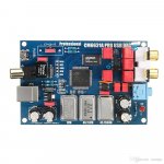
on the first board there ar silver crystals with the labe
TCO 12M MCO 1510A so its a 12mHz crystal with "A" rate = +/- 50ppm working Voltage 5V...see attachment
on the second board it is a SMD
black color smaller size with the "label " B0QMA or its a BOQMA
but i found nothing...
any ideas which sort of crystal that is??...i am asking because i want to know if i should change the crystals (i had a not working board with the bigger shielded TCO MCO crystals)
chris
typo !
the crystals are rate "A" and therefore are + - 25ppm so its fine i guess.
to compare 2 modded boards i will start to do the same mods as the board 1. except the yellow 4700pF at the 9023 outputs and keep the "black SMD B0QMA crystals" in the first step.
chris
crystals - 3,3V
Hi
during my observation about changing the 3,6V for the 9023 i found that all crystals are powered by 3,3V by the regulator. they do not get 5V as i thought...
as the posts before i found a datasheet about the silver crystals MCO 1510A.
so my question is:
the crystals are type A - so recommended 5V but they get 3,3 volt- what happens? are the ppm +/-25ppm foll to weak +/-50ppm?
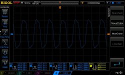
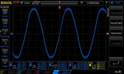
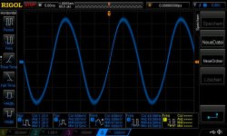
3 pic done with my scope diff probe-strange is that the 12Mhz crystal is oscillating with higher voltage as the other 2 xco are with less voltage.
ideas? advice's?
thx chris
Hi
during my observation about changing the 3,6V for the 9023 i found that all crystals are powered by 3,3V by the regulator. they do not get 5V as i thought...
as the posts before i found a datasheet about the silver crystals MCO 1510A.
so my question is:
the crystals are type A - so recommended 5V but they get 3,3 volt- what happens? are the ppm +/-25ppm foll to weak +/-50ppm?
3 pic done with my scope diff probe-strange is that the 12Mhz crystal is oscillating with higher voltage as the other 2 xco are with less voltage.
ideas? advice's?
thx chris
Attachments
additionally to the previous post i have to add questions too.
the 12mHz crystal sent 4Vpp to the CM6631A....correct? the input expected 3,3V so what happend to the cm6631A?
so for me its clear that the crystals must have 3,3power to put the correct signal to the CM6631A but this crystals are desinged for 5V power supply. so should i change this to the other crystals with right voltage range of 3,3V?
chris
additionally to the previous post i have to add questions too.
the 12mHz crystal sent 4Vpp to the CM6631A....correct? the input expected 3,3V so what happend to the cm6631A?
so for me its clear that the crystals must have 3,3power to put the correct signal to the CM6631A but this crystals are desinged for 5V power supply. so should i change this to the other crystals with right voltage range of 3,3V?
chris
My CM6631A+ES9018 board is ordered and on its way.
Chris, my experience with crystal oscillators is that either they oscillate at very close to the right frequency or they don't oscillate at all. In your case they oscillate since the board works.
I agree the power supply voltage should be raised to 3.6V such that there is no risk of clipping. 3.6V is easy to design for but the noise should be low. Here I have the problem that I am not certain what is sufficiently low (noise). I assume the ES9018 has an internal band-gap reference and that the supply voltage is not used as reference voltage.
The 1117 (and LM317) has 0.003% noise per volt. I assume that is RMS. With 3.6V, that should be 30uV per volt or just above 100uV for 3.6V.
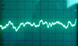
I put a power supply together from ordinary parts and had around 20uVrms noise (one photo is with 50uV per division, the other with 10uV per division). Is that sufficient?
It can handle currents up to 500mA and be modified to do even more.
I noticed the ES9018 has a build-in capacitive charge pump for generating the negative supply. Such is frequently used for USB DACs but also for other DACs because it is easy to use a DC voltage adapter as supply. Then, the charge pump generates the negative voltage. I have three concerns with the use of a charge-pump on a low-noise supply voltage: They generate noise on the supply-line used for their input, they have a noisy output voltage and the negative output voltage is rarely symmetrical with the positive supply voltage but less. In other words, why use a low noise supply just to have it spoiled by a charge pump?
A solution is to generate a symmetrical supply voltage (+/-3.6V) external of the IC, disable the charge-pump by removing the flying capacitor and use the terminal for the negative decoupling capacitor as input for the negative voltage. This way the performance of the low noise power supply is not harmed and the DAC has the possibility to perform the best. Such is doable.
The DAC output filter seems to be a capacitor only. Not a big effort to do the best. I assume it acts as a low-pass filter. I will study some other DAC output filters to see if an improvement is feasible.
At turn-ON I assume there is some noise. It can be solved by a signal relay similar to what is used for loudspeakers.
The initial 1117 regulator can be used for the CM6631A only not to propagate the CM6631A digital noise onto the ES9018.
I am looking forward to receive my board.
Attachments

Hi FF
nice that you want to join here...
i read a lot about some threads...but i really not sure to get this information sorted in my head...
... i just remember that somebody tried the supply of +/- 3,6V for the ES9023 but it get really hot. Jean paul and subbu designed a "subbu DAC" and they recommend do let the charge pump work as the designer plan it
....but why not try this....this exactly your direction.....DIY
but i am afrai that 1 board is sufficient for try something
chris
nice that you want to join here...
i read a lot about some threads...but i really not sure to get this information sorted in my head...
... i just remember that somebody tried the supply of +/- 3,6V for the ES9023 but it get really hot. Jean paul and subbu designed a "subbu DAC" and they recommend do let the charge pump work as the designer plan it
....but why not try this....this exactly your direction...
..DIYbut i am afrai that 1 board is sufficient for try something
chris
Hi Chris,
That was very useful information you gave me. Using Google, I quickly found the thread where in particular Valeriano, J-P and “Hobbit13” discuss the results of removing the charge-pump flying capacitor and using an external symmetrical 3.6V power supply.
Their conclusions are that the charge-pump is well implemented but with an external symmetrical supply the ES9023 sounds better. The delicacy is that the negative voltage rail should only be available when the positive voltage rail is available. Else, the negative chip pin pulls a lot of current.
“Hobbit13”s experiments further conclude on supply currents for both supply pins. They suggest some improvements of component values and recommend the use of an output buffer stage.
The timing for the two supply rails I believe I can manage in an external design. I will probably use current-source feed shunt-regulators as the currents are moderate and rather stable.
They also discuss why the ES9023 is so cheap and still so performing. I realized that ESS has two series of DACs: the audiophile series and the mobility series. The ES9023 is from the mobility series. This is why it is put in a small SOT16-housing, produced in large batches and very cheap. 24 bits is absolutely not bad. You are an experienced audiophile and have heard how well it sounds even before improvements. The SOT16 housing we can handle, the audiophile series chips are in housings with pins on all 4 sides and very tiny.
I will start looking for components for a symmetrical external 3.6V power supply.
Hi Chris,
That was very useful information you gave me. Using Google, I quickly found the thread where in particular Valeriano, J-P and “Hobbit13” discuss the results of removing the charge-pump flying capacitor and using an external symmetrical 3.6V power supply.
Their conclusions are that the charge-pump is well implemented but with an external symmetrical supply the ES9023 sounds better. The delicacy is that the negative voltage rail should only be available when the positive voltage rail is available. Else, the negative chip pin pulls a lot of current.
“Hobbit13”s experiments further conclude on supply currents for both supply pins. They suggest some improvements of component values and recommend the use of an output buffer stage.
The timing for the two supply rails I believe I can manage in an external design. I will probably use current-source feed shunt-regulators as the currents are moderate and rather stable.
They also discuss why the ES9023 is so cheap and still so performing. I realized that ESS has two series of DACs: the audiophile series and the mobility series. The ES9023 is from the mobility series. This is why it is put in a small SOT16-housing, produced in large batches and very cheap. 24 bits is absolutely not bad. You are an experienced audiophile and have heard how well it sounds even before improvements. The SOT16 housing we can handle, the audiophile series chips are in housings with pins on all 4 sides and very tiny.
I will start looking for components for a symmetrical external 3.6V power supply.
You are awesome !!!
here is the thread what you/we are talking about:
https://www.diyaudio.com/forums/digital-line-level/197486-measurements-es9023-dac-6.html#post3484937
https://www.diyaudio.com/forums/digital-line-level/197486-measurements-es9023-dac-6.html#post3484937
Hi Chris,
I got my CM6631A+ES9023 board yesterday. Plugged it in with a Windows lap-top and played some FLAC-files. Even without modifications it sounds fine. Did only a few aesthetic improvements.
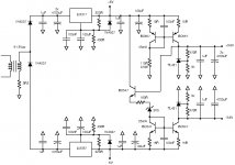
I will buy components to make a dual 3.6V power supply according to the schematics I appended. I have to be careful in which order and with which timing I power up the different parts of the board. The +/-6V may be used for an output buffer/filter.
Enjoy the weekend.
I got my CM6631A+ES9023 board yesterday. Plugged it in with a Windows lap-top and played some FLAC-files. Even without modifications it sounds fine. Did only a few aesthetic improvements.
I will buy components to make a dual 3.6V power supply according to the schematics I appended. I have to be careful in which order and with which timing I power up the different parts of the board. The +/-6V may be used for an output buffer/filter.
Enjoy the weekend.
Attachments
Last edited:
...update...2nd board is modified to 3,5V via Mic5205...
Hi
yesterday night i did the modification of the 2nd board with the power supply for the ES9023 DAC via Mic5205. i use a small pcb to sold the SOT23-5 and add a SMD 4,7µF tantal on both ends (Cin, Cout), ...
Adafruit SMT Breakout PCB fur SOT, 23, SOT, 89: Amazon.de: Computer & Zubehor
i test the regulator with a small load(watch out the max current is 150mA- i use 6kR) and the Voltage was about 3,596V...its working !
the Cbyp= 470pF its still on the way/ordering...
i implement the regulator at the board. the input i soldered at the AP2114 and the output 3,6 i soldered as near as possible to the ES9023.
one pcb trace you have to cut !!
look at the pic
red cut the trace
blue new supply 3,6V
add the resistor with 130k ohm at pin 6 (setup for 3,6V) i use a 0603 smd and its too small...use a smd 1205 and it would fit better...
other changes are like the other board = change the caps and the regulator. at the regulator small 10µF/16V SMD caps are used and the crystals are different at this board...
finally the board is "singing"/playing so it works...sound check will follow...
pic of the board will be today eveneing
chris
Hi
yesterday night i did the modification of the 2nd board with the power supply for the ES9023 DAC via Mic5205. i use a small pcb to sold the SOT23-5 and add a SMD 4,7µF tantal on both ends (Cin, Cout), ...
Adafruit SMT Breakout PCB fur SOT, 23, SOT, 89: Amazon.de: Computer & Zubehor
i test the regulator with a small load(watch out the max current is 150mA- i use 6kR) and the Voltage was about 3,596V...its working !
the Cbyp= 470pF its still on the way/ordering...
i implement the regulator at the board. the input i soldered at the AP2114 and the output 3,6 i soldered as near as possible to the ES9023.
one pcb trace you have to cut !!
look at the pic
red cut the trace
blue new supply 3,6V
add the resistor with 130k ohm at pin 6 (setup for 3,6V) i use a 0603 smd and its too small
...use a smd 1205 and it would fit better...other changes are like the other board = change the caps and the regulator. at the regulator small 10µF/16V SMD caps are used and the crystals are different at this board...
finally the board is "singing"/playing so it works...sound check will follow...
pic of the board will be today eveneing
chris
Attachments
Last edited:
- Status
- This old topic is closed. If you want to reopen this topic, contact a moderator using the "Report Post" button.
- Home
- Source & Line
- Digital Line Level
- CM6631A + ES9023 cheap board - modification...?