This particular board exists in various versions. Does yours have the beads in the power supply lines? You definitely have power supply issues so a good first would be replacing the 1117 and give the ES9023 a separate reg.
Please use the datasheet values 4.7 nF for output filtering.
first...you are quick in answering...😉thx
caps i have just 4,7nF ceramic at home ok?
regulator is just ald117 3,3 sot 223 at home..
which bead do you mean...i do some pics...no idea
chris
No do things right the first time otherwise you will loose time and possibly damage the PCB when you do find it needs the original tested values. You need good quality film caps that fit physically (preferably FKP or styroflex or the like) and AFAIK the board has pads to solder those. If you don't have them right now then simply order them together with all the stuff you will need. Choose better regs that have the same pinout as the 1117. For the ES9023 you will need a 3.6V regulator and a TO92 version would be most handy but I am afraid these do not exist so it will be careful implementing a SOT223 one or just use the MIC5205 in 3.6V.
The beads are the ferrite cylindric shaped parts as shown on the CM6631 + ES9023 boards that are sold now. So newer boards have these. They filter out high frequency signals as they form a higher impedance for those frequencies. Lower frequencies like DC (😉) are not hampered.
The beads are the ferrite cylindric shaped parts as shown on the CM6631 + ES9023 boards that are sold now. So newer boards have these. They filter out high frequency signals as they form a higher impedance for those frequencies. Lower frequencies like DC (😉) are not hampered.
Last edited:
Thanks. Please note that the XO power supply pins are opposite to eachother in a diagonal. You probably can use SMD caps straight from the + pin to the GND plane if you scratch away a bit of the blue coating. I would use 0.1 µF 0603 (if that is correct, please check size).
The 1117 is famous for noise which is (depending on manufacturer) around a whopping 100 µV. I would replace it anyway also when it only feeds the XO's.
That’s in fact the board I was looking at while wondering where the decoupling was.
I use either .01 x7r, by itself or if there’s room, will sometimes use a 1000pf cog, along with the .01 x7r.
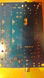
I noticed some pads in that view of the underside, and they didn’t make any sense to me.
Same here 🙂 However on the pics chermann attached we can see it is C18, C21 and C23 that are pads for decoupling caps. 0.1 µF X7R are just fine for this.
Last edited:
hi
please i am a noob/old man...not too fast pleas
so i have to order for the output of ES9023 the correct valus 4,7nF fkp or styro..
so nothing at home so i have to.
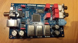
the caps i refer at the very first post and is in the pic 1 in the red circle these 2 wima 220/100V ("5") marked caps where soldered ...and i put is wrongly out.
so which beads to refer??
thx chris
please i am a noob/old man...not too fast pleas
so i have to order for the output of ES9023 the correct valus 4,7nF fkp or styro..
so nothing at home so i have to.
the caps i refer at the very first post and is in the pic 1 in the red circle these 2 wima 220/100V ("5") marked caps where soldered ...and i put is wrongly out.
so which beads to refer??
thx chris
Check if Wima FKP 4.7 nF exists in 5 mm pitch and order those. Your board has the beads so no worries. It still is noisy so we have to improve it I think. I don;t have too much time these days but I would advise to first check and make a list of what you will need in total and then order it. There is no need for hurrying.
You will also need better quality tin/lead solder and some isopropyl alcohol for cleaning the PCB. I see a through hole resistor is used by you but please use SMD parts in this DAC.
I just checked and it is partnumber FKP2C014701D00HF00 for the Wima caps.
You will also need better quality tin/lead solder and some isopropyl alcohol for cleaning the PCB. I see a through hole resistor is used by you but please use SMD parts in this DAC.
I just checked and it is partnumber FKP2C014701D00HF00 for the Wima caps.
Last edited:
Check if Wima FKP 4.7 nF exists in 5 mm pitch and order those. Your board has the beads so no worries. It still is noisy so we have to improve it I think. I don;t have too much time these days but I would advise to first check and make a list of what you will need in total and then order it. There is no need for hurrying.
You will also need better quality tin/lead solder and some isopropyl alcohol for cleaning the PCB. I see a through hole resistor is used by you but please use SMD parts in this DAC.
Partnumber is FKP2C014701D00HF00 for the Wima caps.
ok thank you JP..
just to clarify...my measurements i did directly on the AMS1117 chip...so not after the ferrite beads or at the es9023
It does not matter right now as the 1117 already is junk and since there is only one regulator feeding everything it is no surprise you see noise as it also feeds the 3 x noisy XO's that pollute the supply line. Remeasure when a better reg is used. Now you can spend some time finding a suitable low noise reg and think of a layout how to implement it (together with decoupling caps) neat and tidy with shortest possible connections on the PCB. Gotta go now, sorry.
You could measure at the ES9023 but I think I already know how that will look like 😀
You could measure at the ES9023 but I think I already know how that will look like 😀
Last edited:
Same here 🙂 However on the pics chermann attached we can see it is C18, C21 and C23 that are pads for decoupling caps. 0.1 µF X7R are just fine for this.
At first glance the pads looked as if they connected the output to ground.
I couldn’t imagine having nothing for decoupling on clocks!
On one of my boards, the supplied ferrite had a single pass of the wire through the core, I replaced it with one like this for a further reduction of noise.
Wire Ferrite Beads - Laird-Signal Integrity Products - Beads and Chips | Online Catalog | DigiKey Electronics
Hi phase
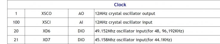
so back to the crystals
so i interpret. exactly where is written C18, C21 and C23 there should be decoupling caps:
JP wrote 0,1µF X7R ceramic is good.
you wrote 0,01µF X7R+ 1nF C0G ceramic
and this ferrite coils ?
thanks for your time
chris
so back to the crystals
so i interpret. exactly where is written C18, C21 and C23 there should be decoupling caps:
JP wrote 0,1µF X7R ceramic is good.
you wrote 0,01µF X7R+ 1nF C0G ceramic
and this ferrite coils ?
thanks for your time
chris

The easiest thing to do, and probably what you should do first, is to look at what the pinout is on a vcxo, and then look at your traces and pads on the underside of your board.
That will tell you where the vdd or power pin will be. Then do the same for the ground, then identify which solder pads are associated with those.
That is where you will want to place any decoupling, between power and ground. I would start with the .1uf, then expiriment later.
The other possibilities for improvement after that may include using a ferrite in series on the power, on the regulator side of that decoupling capacitor. Also, if there is room, you may try the other arrangement using the 1000pf+.01uf. You have to balance any potential performance increase with the risk of removing a trace also in situations like this. Quite often I will settle for something more simple just to avoid issues with such a hacked installation.
It all depends on how damage prone the parts will be once installed, and how the board is handled after or during the work.
Keep in mind reliability is a function of performance and you may end up needing to replace the entire board if it becomes too damaged. For that reason I would recommend just using a single capacitor and the ferrites in series on each of the vcxo. Just be careful to not lift any traces.
Good morning Phase
thank you
The easiest thing to do, and probably what you should do first, is to look at what the pinout is on a vcxo, and then look at your traces and pads on the underside of your board.
That will tell you where the vdd or power pin will be. Then do the same for the ground, then identify which solder pads are associated with those.
I checked the traces and the caps C18, C21 and C23: it is as you described..
what about C19,C22, C20?...i checked this the traces go to the CM6631A chip...see attachment
chris
Attachments
Hi I think placing the caps on C18, C21 and C23 is a one chance only affair. Chinese PCB material is not suitable for reworking a few times. It is up to you. I just saw your list of parts and please get accustomed to using SMD parts. SMD beads are way easier to use on traces (just cut the PCB trace and solder the bead over the gap). You need beads that are ultra low impedance for DC and higher impedance for high frequencies. You can look up the part list of Subbu V3 for a suitable version. In fact you can adapt this ES9023 design with most V3 values/design choices.
Again I think you need better soldering tin and/or soldering tool. In german speaking countries Fluitin 1532 (in 0.5 or 0.7 mm) is available which is excellent. Cleaning the board is essential after reworking.
* C19,C20 and C22 are pads for caps to GND from the output of the XO's. I would not put caps there.
Last edited:
Hi I think placing the caps on C18, C21 and C23 is a one chance only affair. Chinese PCB material is not suitable for reworking a few times. It is up to you. I just saw your list of parts and please get accustomed to using SMD parts. SMD beads are way easier to use on traces (just cut the PCB trace and solder the bead over the gap). You need beads that are ultra low impedance for DC and higher impedance for high frequencies. You can look up the part list of Subbu V3 for a suitable version. In fact you can adapt this ES9023 design with most V3 values/design choices.
Again I think you need better soldering tin and/or soldering tool. In german speaking countries Fluitin 1532 (in 0.5 or 0.7 mm) is available which is excellent. Cleaning the board is essential after reworking.
* C19,C20 and C22 are pads for caps to GND from the output of the XO's. I would not put caps there.
Hi JP
thank you for your time and inputs.
i have a complete metcal solder and desolder equipment and i am an ee...but no experience in audio..yes i agree on the chinese pcb quality ...they are not really good for lot of reworks. this board is not as bad........i always use a pcb cleaner😎
i will check my list...if it was not to late yesterday i should prefer SMD😉
i check to find subbu v3 BOM list..
thx
chris
When I first saw all those solder pads I knew they couldn’t all be used as this would hamper the signals.
When working with boards like that, I will often budget for a second board to modify once the values and configuration have been established. I hope the smd beads enable the desired noise reduction, maybe a series of the smd beads will offer better performance than a single bead.
I love my Metcal iron!
hi phase
.i completely agree with you...
i learnt a lot at this journey:
https://www.diyaudio.com/forums/class-d/309813-wrong-tpa3255-77.html#post5701127
yes i plan/budget more then 1 board for this mod´s..i have 1 and the 2 boards are on the way.
chris
.i completely agree with you...
i learnt a lot at this journey:
https://www.diyaudio.com/forums/class-d/309813-wrong-tpa3255-77.html#post5701127
yes i plan/budget more then 1 board for this mod´s..i have 1 and the 2 boards are on the way.
chris
Hi
Waiting for the other board i start with the topic USB isolator
i bought a ADUM4160 about 18 Euro at amazon
DollaTek USB Isolator 1500V Isolator ADUM4160 USB-zu-USB-Isolatormodul Audio-Rauschunterdrucker Industrieller Isolatorschutz: Amazon.de: Elektro-Grossgerate
the Sound check with the CM6631A board and my Topping D50 DAC is successfully. as i read the max audio format with this adum is 24Bit/96kHz...fine i can l live with that.🙂
the adum is directly connected after the laptop and powered with a different USB port as external power supply...therefore you have to set the switch.
pic 1
first i start with topping D50 and i take 1 setting and reboot to have win recognize the adum+D50.
i tried a month ago a ifi audio i usb3.0 nano (220 euro) but had no big approvements ! this adum is really good and i can really recommend this box
sound gets sorted, darker, bass controlled, more "right" sound
CM6631A board
first.......... every connect/disconnect force a notable pop in my chain -speakers🙁
the max audio format after i tried several time with win setting is 24/48kHz...its not possible to get more😕... pic 2
any comments or hint to solve that is very wellcome 😉😀
nevertheless the sound improvement is really good🙂....the difference is the same as at the D50...the small DAC get more air and 1 step deeper sound stage
so the low cost DAC grow from 35euro +18euro(adum)....😉
chris
pump up...from post 8
some Cmedia + win experts here...?😉
chris
- Home
- Source & Line
- Digital Line Level
- CM6631A + ES9023 cheap board - modification...?