Excellent news, bravo for your relentess R&D!
How are the OPAs implemented for Kubelik? Is there a socket on which we can simply take in and out OPAs to do some amp rolling, possibly also try SMD OPAs using our own small adapter boards?
On another note, reading your comment, my understanding would be that you hadn't the right sound with 3 DAC chips, an acceptable one with 6 but that you could be heapier with more hence looking into 12 or possibly even 24... correct?
Thanks again for sharing all this
Claude
Hi Claude - no, no sockets. With a kit you can decide which opamp to fit, if you don't like your first choice you'll need some de-soldering braid and maybe a sharp blade knife to lift pins. De-soldering SOIC-8s isn't too onerous. The opamps are already SMD to have a nice compact design (5 * 8cm approx).
I feel the 3 DAC chip sound was acceptable but then when I tried more chips (I'm forever curious about tweaks) there was an improvement so I asked my wife how many more chips she felt she could fit on the PCB (as she does all the PCB layouts for me). She said she'd try for 6 and has achieved that, quite remarkably! I have built one prototype with 12 chips but diminishing returns seems to be setting in - perhaps for more chips I need a lower noise I/V stage. I think then the benefits of the extra chips may shine through. Six chips seems to be a fairly good match for the JFET opamps I'm currently using.
I feel the 3 DAC chip sound was acceptable but then when I tried more chips (I'm forever curious about tweaks) there was an improvement so I asked my wife how many more chips she felt she could fit on the PCB (as she does all the PCB layouts for me). She said she'd try for 6 and has achieved that, quite remarkably! I have built one prototype with 12 chips but diminishing returns seems to be setting in - perhaps for more chips I need a lower noise I/V stage. I think then the benefits of the extra chips may shine through. Six chips seems to be a fairly good match for the JFET opamps I'm currently using.
For those curious what improvements come from adding more chips, its primarily in the LF in that the acoustic space seems to be rendered more truthfully and when the music gets more complex there's less of the tendency for the whole acoustic image to shift slightly forward. My wife says that decays are easier to follow into the noise with more chips. Which is what I'd expect - with a CMOS DAC chip like TDA1387 there's noise which isn't flat with frequency, it rises at LF so paralleling seems to bring most benefit in that region.
There is also the impression of slightly greater 'tonal density' (to borrow a 6moons phrase) with more chips, but this is rather secondary to the LF improvements in my estimation.
Adding more chips does allow the I/V stage to use lower resistor values and that lowers the noise overall - on Kubelik r2 the I/V feedback resistor noise is similar to the opamp's intrinsic noise so going to 12 chips will leave the opamp itself as the dominant noise source in this stage.
Sockets suck with the fast nowadays oaps…that deserve you try them! ClaudeG you should avoid it if you want to test several oaps. I'm sure you are aware already.
What you can do is using a flat pcb adaptor. On which you solder pins/leads from electronic wastes: we always have solid copper tinned leads from caps, diodes, resistors. Solder 8 on your pcb adaptor, thick enough for a good contact in the vias/holes of the dac pcb.... without soldering: it's just for testing purpose.
Of course it's not perfect, but it reduces for testing purposes the dip8 adaptor that sucks with fast oaps.
OAPS : 1611/12; 1602; 810;1656, etc, the ones you are talking about in relation to the load to drive as well, etc :many worthing a try related to the circuitry and the next load you have") .
.
Ask Abraxalito if the oap you want to test is compatiblr with the electic values of his design or not -
What you can do is using a flat pcb adaptor. On which you solder pins/leads from electronic wastes: we always have solid copper tinned leads from caps, diodes, resistors. Solder 8 on your pcb adaptor, thick enough for a good contact in the vias/holes of the dac pcb.... without soldering: it's just for testing purpose.
Of course it's not perfect, but it reduces for testing purposes the dip8 adaptor that sucks with fast oaps.
OAPS : 1611/12; 1602; 810;1656, etc, the ones you are talking about in relation to the load to drive as well, etc :many worthing a try related to the circuitry and the next load you have
.Ask Abraxalito if the oap you want to test is compatiblr with the electic values of his design or not -
Last edited:
Thanks Diyiggy
Yep, well aware indeed, playing with op amps since a few decades, of course not blind op rolling.
Having said that... I found out that when in audio frequencies band and usual signal impedances, after all a socket didn't hurt the sound for me at all. Nor 2 quality ones stacked... at 3 it started to have a slight impact. I tried that on a HP amp project, with my HP directly connected, so quite revealing... was an interesting experiment, I was just curious and really expect the opposite finding.
I was for decades an advocate for soldering only and direct path and no caps etc. and yet my latest audio project, the VFET amp, has crimped connections, I added screw connectors for my numerous tests (can't be good) and its Front End has, horror, a cap in the signal path and even an Eldor transformer at the output directly in the signal path. Can't be good at all, for sure!
I bypassed the entire FE section, all this, and.. heard no change in the sound. Go and figure... Nor a friend experimenting with me... and we tried really hard, as it couldn't be, and we are quite focussed when it comes to comparing parts etc. as you perhaps know. To no avail, go and figure...
At the end for me connectors and crimping are acceptable, some components in the signal path can be ( warning! "at lower frequencies and acceptable impedances / loads") acceptable (but ofcourse it is very different at HF digital signal transfer!) and sockets are OK given some impedance and frequencies limitations. So all depends what the opa are doing and where probably...
Perhaps more importantely here... I suspect the FE bypass made so little impact because the following Output Stage dominates the sonic signature, as that FE isn't 100% transparent of course.
Bottom line here: op amps may perhaps have less impact than anticipated if the output transistors dominate the sonic signature... IF being the key word.
Back to topic, the OPA1656 could be a candidate for me, and it is of course compatible given its topology. Whereas soldering in and out SMD resisors etc is very straight forward, I must say I struggle with multilegs devices, admittely far more than 8, using a soldering iron with flat tip and/or desoldering machine. I don't have more equipment and it all ends usualy in cutting legs. No drama, at least I never damaged a board or other components.
Your idea gave me perhaps another one though, while at the pool enjoying the sun (so might be BS LOL)... using a PCB adapter for small OPAs and soldering indeed small leads (I always keep them in a small bag,various length and diameters, handy) on it, say 1.5cm or so,that I could slightly bend one end to make a plateform to solder on the original PCB intended for said small OPA. Advantage: this legs are easier to cut or desolder, and the OPA on a small board aswell should I need it. Inconvenient: well, long legs to have that raised plateform, to enable a soldering iron to reach underneath...
What a strange legged tower, with a flat platform, just to experiment first of course.. need to think about it with a cold mind LOL
Have fun!
Claude
But if you need for such a platform "long" leads for bending, do you not go back to the same defaults than a dip8 adaptor ?
If that chip is a current output dac chip, one can try what Vunce member did an oap 861 smd to DIL8 adaptor I/V board. He generously gave the gerber to the DIY comunauty so it's cheap enough to worth a try. You can find the link to the first page of the Miro1360 thread about the AD1862 DAC.
And if the Abraxalito design is using a voltage output Philips dac chips, well forget it for the better oaps you talk about. there are a lot to try, are they compatible to this design, I don't know : OPA8620; AD8599 ; OPA2192, AD4627 as well to add to the list of the nice enough oaps.
Hi Richard. I guess you are referring to the attachment of that post lingDAC - cost effective RBCD multibit DAC designGeorge - what was your test result done on?
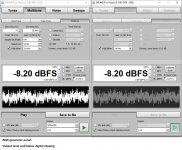
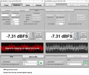
It is a table showing the clipping warning level of REW’s signal generator
REW generator issues a warning when it's output level exceeds a threshold.
Warning is: "Signal is clipping at digital full scale".
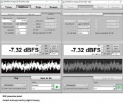
The detection of clipping is done at the digital level, upstream of each sound card’s analog out and any potentiometer that adjust the analog output of the soundcard. Clipping detection level has a resolution of 0.01dB.
For every waveform type there is a different clipping level.
To check the validity of that auto detect level, I looped-back the E-MU 0404 analog output to it’s analog inputs, lowered the hardwired output level so that card's inputs are way below their high levels and measured with REW's RTA the IMD of a multitone test. See last attachment for test results
And please accept my humble respect for your persistence in searching for improving your DAC.
George
Attachments
-
 1 away from digital clipping.jpg200.5 KB · Views: 201
 -
 6 IMD plot.jpg106.6 KB · Views: 78
 -
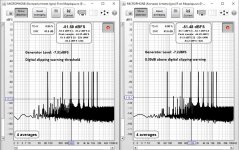 5 spectrum at and into digital clipping.jpg267 KB · Views: 178
 -
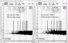 4 spectrum away from and approaching digital clipping.jpg263.2 KB · Views: 193
 -
 3 digital clipping.jpg208.3 KB · Views: 199
 -
 2 approaching digital clipping.jpg203.1 KB · Views: 198
Oh, on second thought after more drinks by the pool, I guess it was a bad idea. Simple and effective: soldering directly in and out SMD op amps, be it worst case at the cost of cutting legs. After all, layout is easy to access in this project
Having said that, the current choice shlould do a good job for that kind of function and regarding adapters, pretty sure here they wouldn't have affected the sound AFAIC...
Let' see...
Claude
Having said that, the current choice shlould do a good job for that kind of function and regarding adapters, pretty sure here they wouldn't have affected the sound AFAIC...
Let' see...
Claude
If that chip is a current output dac chip, one can try what Vunce member did an oap 861 smd to DIL8 adaptor I/V board.
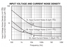
That would require a design change as the OPA861 is an OTA, not a standard opamp. Whilst the '861 is an attractive part in some respects its relatively noisy and they're not showing just how noisy below 100Hz.
And if the Abraxalito design is using a voltage output Philips dac chips, well forget it for the better oaps you talk about. there are a lot to try, are they compatible to this design, I don't know : OPA8620; AD8599 ; OPA2192, AD4627 as well to add to the list of the nice enough oaps.
TDA1387 is current-output.
@George - thank you very much for your comprehensive reply.
PCB layout
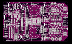
Here's how the r2 Kubelik PCB looks.
The inductors can be either P14s which I'm sourcing locally or if you want to source parts yourself you can use 22mH Bourns RL181S from Mouser. They do have stock right now (~1500) but who knows for how long?
We deleted the phase switch as that's just BOM cost bloat. Now the phase is switched by soldering a 0805 resistor in one of two positions. Inverted phase can be used for building a fully balanced Kubelik with two boards and 12 DAC chips
Attachments
Richard you are welcome.@George - thank you very much for your comprehensive reply.
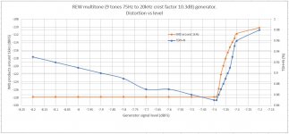
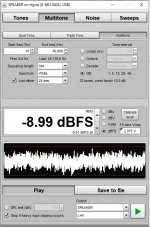
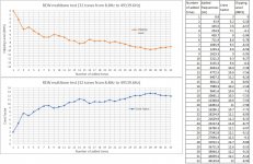
Still in REW, I was curious to see the reported crest factor and the reported digital clipping level when building multitone test signal by adding one frequency at a time.
When SR is 192kHz, 32 individual tones can be added one by one, starting from the lowest 8.8Hz.
Results below.
George
Attachments
That would require a design change as the OPA861 is an OTA, not a standard opamp. Whilst the '861 is an attractive part in some respects its relatively noisy and they're not showing just how noisy below 100Hz.
Ears less sensible in that frequencies ? Or group delay of loudspeakers and room modes below Schröder frequency bad enough to care less of the oap noise below 100 hz ? Where is the step ?
Anyway thanks for that input.
I believe P. Rodgic still uses it today, he likes the non feedback things added to a big transconductance. TDA151 + CCS with a N-Fet then an opa861... he also use two smt transistor in in his on shelf top line. But I don't know in which typology. I have the simple version with the oAP861 and it subjectively sounds good : fast, good chest effect, natural voices and clearness; tones good enough while here it's also always about the power supply and caps for the tones to find a good enough equilibrium.
@diyiggy - I must be missing some context as I can't decode your questions. I am attaching the noise plot for OPA861 - you'll note the frequency axis to the left stops at 100Hz whereas I'd really like to see what happens all the way down to 20Hz.
I don't doubt that it sounds good, just that I reckon if it were lower noise it would sound even better. Low frequency ambience on recordings seems to me to be delicate and needs attention to its preservation so as to appreciate the acoustic signature of the recording space fully.
@George - if you're interested in reducing crest factor in multitones, you might be interested in this paper : http://conf.e-jikei.org/ICTSS2018/proceedings/materials/proc_files/IPS03/IPS03_08_ICTSS2018.pdf
Attachments
Last edited:
Thanks Richard. These too:
https://web.stanford.edu/~boyd/papers/pdf/multitone_low_crest.pdf
https://www.elektronikfokus.dk/wp-content/uploads/sites/5/AppNote71-MULTI-TONE-TESTING.pdf
Multi-tone Signals -Part 1
My understanding is that test signals with high crest factor are able to better reveal any non linear behaviour of an audio DUT but test signals with lower crest factor are closer to real music signals (certainly so for contemporary music). The high research activity toward low crest factor test signals is due to the applicability of such signals to the telecommunication world.
Searching on the topic, I read this paper. I hadn’t heard anything about this test signal, although it was an outcome of BBC research since early seventies and it targets audio.
https://orca.cardiff.ac.uk/74984/1/TIM2450296.pdf
George
I first came across the 'Schroeder phase multitone signal' when I was working on studio consoles and we wanted a way to directly measure the frequency response of a chain of EQ circuits so we could guide the operator to set the controls to a previously stored position.
I think higher crest factor is more revealing of non-linearities but also has a lower average level meaning for measurement its going to reduce the SNR and hence isn't too desirable. Lower crest factor makes a lot of sense when the aim is a quick (but not too dirty) measurement of FR.
I think higher crest factor is more revealing of non-linearities but also has a lower average level meaning for measurement its going to reduce the SNR and hence isn't too desirable. Lower crest factor makes a lot of sense when the aim is a quick (but not too dirty) measurement of FR.
What is strange with that opa861 is you can not feel any quality lack in the sound quality in the low frequencies you talk about . Subjectively, quite the opposite, in fact. Again, the bass are good, tight but not dry though powerfull without mask effects; very clear and informative/detailled; accurate tones with the male voices of barytons : & tenors, so >80 hz in their low end voice. No problem with bass string and piano resonances on the low notes with pedals.
In fact this combo beats all the modern delta sigma high end I heard in that department. For instance a Soekris R2R if subjectively got the feeling to go low, it is very borring and flat as an oil sea instead! Notice there are very few recording with something between 20 hz to 40 hz but if you spend the day at listening Moussorgski. And again I surmise the room problems will dictate over the noise in that area.
So maybe there is few correlation here with the final rendition and that noise measurement - I highglighted the low sensibility of ears with distorsion in the low area you talk about as perhaps an explain?. Maybe you're an headphone guy though which are moreprecise below 100 hz than most loudspeakers in a room?
I know a guy that own both your DAC and a Rogic's DAC, I would be curious to read his conclusions as I know he is both a loudspeaker and an headphone enthusiast.
That's the problem with datas, sometimes the ones we focus onto are perhaps not the most important. OPA861 based dacs exist and sound very good and were made by experienced audio designers. Maybe in the trade offs of this opa861, the non feedback (hence the noise ?) is subjectivly sounding better as a tube could be noiser but have in an ABX a better listening approval ?
I don't know but I ask and just write my doubt. ANyway Rogic wrote a paper you can find on Audial website where he compares a diamond stage from an AD844 with sorted out discrete bjt. The noise floor of the AD844 is on paar and he said one will be have hard time but a difficult sorting out to do better than the discrete here in term of noise floor if I understood correctly. It's also my understanding he found better the further OTA 660 and 861 both used as the AD844 with no feedback.. I also assume the TDA1541A is a better DAC chip that the one you chosen for its aviability and low price in the chineese local market.
I also notice most designers using opa for easyness in spite of complex discretes I/V and buffers are nowadays using some said sota opa as the 1656, the 1642, 1602, 810, even with modern DS dac chips with current output when existing ! So not that opa861. Maybe designers don't like to copy themselves, I don't know ! Anyway on a datasheet point of view, all the brands jumped on that opa1611/1612 when th noise floor and I/V were a concern with the ESS dac chips !
FOr my limited experience and view from a non EI with just a tweaking experience : often it's simply a power supply choice that can make such stages sing right or not... I think it's a great part of a design, certainly not the most exciting for an experienced designer as you -though you spent some times on power supplies if I remember your blog- But sure it's a whole. With Audial, I surmise the good sound comes as well about the care spent on the power supply : multiple regulated separated rails.
So no final conclusion, just remarks and hope the decoding of what I've said is clearer with this post.
I continue to have a look of you oaps choices that are always originals (price and aviability as important factor?)...
Last edited:
Hi diyiggy - yes I can understand your post this time much better thanks
The noise issue at present I haven't confirmed, its just a conjecture based on listening which correlates with the noise performance of various opamps. Correlation isn't causation.
As regards to your listening remarks about OPA861 I would not expect noise to affect the timbre of male voices unless it had become seriously bad. Here the noise is at a very low level and mostly I notice it effects the ambience. Yeah few recordings (organ excepted) have foreground info below 40Hz but here I'm talking about background info. I can't think why room problems should obscure noise issues in electronics.
No, I'm not mainly a headphone user, I just use them from time to time. Most of the time I'm listening on speakers, near-field.
As to AD844 I went to the DS and its even less revealing about noise than OPA861 in the lower freqs. All noise numbers are given for 1kHz and higher. Yes I would expect TDA1541A to have better LF noise than a single TDA1387 primarily because its bipolar tech (not CMOS) but I'm using multiple paralleled chips which definitely improves the ambience retrieval. So the jury's out when comparing a single 1541A versus 12 paralleled 1387s.
I do vaguely recall an anecdote that Ayre were using AD844 in a CD player and ADI changed the process which resulted in Ayre rejecting quite a lot of chips. But the newer (presumably die-shrunk) chips were still meeting datasheet specs so Ayre couldn't really complain. My hypothesis here is the newer process had poorer LF noise - I understand Ayre were paralleling chips for this application which tends to suggest they found lower noise in paralleling.
Last edited:
- Home
- Source & Line
- Digital Line Level
- lingDAC - cost effective RBCD multibit DAC design