Listening test:
Q1 to Q4
Q1 seems slightly more dynamic than Q4 throughout the tracks and possibly more open sounding with Q1 having a less defined edges.
Q4 seems more focused, slightly harder tone maybe.
Difficult to say which i prefered , couldnt take one over the other but enjoyed both.
Was expecting a more old style multibit sound for some reason.
Thanks for giving us a sound test, unusual for someone to upload actual audio examples. Very much appreciated.
You take it out of context. I am contending the common misconception that measurements are objective for the humans. There are only objective for FFT analyzers due to the using similar DSP technology at the DAC and at the analyzer. Our hearing is different, which means a current DSP measuring methods completely miss what is important to our ears and in reverse.@sajunky I'm not expecting an order from you as you have said on the Denafrips thread :
[...]
Watch my lips - our hearing is subjective.
In other words, I would never buy from a developer who takes measurements only as a whole truth and disregards listening tests. Do you belong to a such pack?
I do always support your projects and there is a proof everywhere. If you think otherwise, look at your own signature:
We shall not grow wiser before we learn that much that we have done was very foolish - F.A. von Hayek
Last edited:
Are the ceramics x7r or NP0/C0G type on the filter section? I know C0G ones are not cheap but I just needed to ask this.
Another thing is I wonder would @abraxalito support if anyone attempt to build 7th order filter (by following schematic) with through hole components, polystyrene caps, air core inductors etc. I'm not arguing about implementation but I like the idea of putting some own effort even it may cost more.
Another thing is I wonder would @abraxalito support if anyone attempt to build 7th order filter (by following schematic) with through hole components, polystyrene caps, air core inductors etc. I'm not arguing about implementation but I like the idea of putting some own effort even it may cost more.
@terranigma. I am not sure whether air core inductors are appropriate due to the large surface area and difficulties of shielding. As for other components, it looks interesting, thanks, will be watching.
Are the ceramics x7r or NP0/C0G type on the filter section? I know C0G ones are not cheap but I just needed to ask this.
They're NP0/C0G. Having tried to build filters with X7R (first generation lingDAC) its not practical to attempt such close tolerances with them as their value changes over time and temperature.
Another thing is I wonder would @abraxalito support if anyone attempt to build 7th order filter (by following schematic) with through hole components, polystyrene caps, air core inductors etc.
Happy to provide support on that idea right now. I went to Mouser and looked at polystyrene caps - found that the highest value they stock is 10nF. So you'll need rather a lot of these (my guess is of the order of 150 in total). That'll take up quite a lot of PCB real estate as these caps are 10mm*12mm. If you can place them all side by side with no gaps you'd likely need a PCB around 13cm on each side.
The inductors will also be relatively bulky and will need to be spaced apart to minimize mutual inductances. Some experiments will be needed (in simulation) to see what Q is needed to get an acceptable frequency response - its likely that my P14 ferrite cored inductors have higher Q than is really needed. The lower the Q of the inductors the smaller they can be.
None of this is intended as discouragement for your idea, it will be an interesting experiment to try. It won't fit above the Phihex as the existing filters do so getting a low impedance connection to the groundfill might also prove a challenge.

Any talk about orders, pricing ect. should continue there:
PhiDAC hex kits with pre-built filters
Let this technical thread deal with technical discussion and listening impressions only.
George
Listening test:
Q1 to Q4
Q1 seems slightly more dynamic than Q4 throughout the tracks and possibly more open sounding with Q1 having a less defined edges.
Q4 seems more focused, slightly harder tone maybe.
Difficult to say which i prefered , couldnt take one over the other but enjoyed both.
Was expecting a more old style multibit sound for some reason.
Thanks for giving us a sound test, unusual for someone to upload actual audio examples. Very much appreciated.
While this is a interesting test to hear the different presentation between the two, the problem remains that it is being re-encoded by my onboard soundcard and then decoded by your system. I wish I knew what an old style multibit system sounded like so I could do an A/B comparison there. All I know is that the original single chip reminds me alot of that tube sound that my great uncle's system had. It reminds me of vinyl records, big speakers, Lazyboy recliners and thick carpet. Very comfortable 😉
Some measurements?
Thank you for response. You have points to really to be considered. I can't argue with that.
7th order filter took my attention with that smooth 18khz sine wave. It seems you really overcome most serious challenges of NOS concept. But what about some other plots like Dynamic Range, THD, IMD, Crosstalk? Can you give some plots if you are curious too?
None of this is intended as discouragement for your idea, it will be an interesting experiment to try.
Thank you for response. You have points to really to be considered. I can't argue with that.
7th order filter took my attention with that smooth 18khz sine wave. It seems you really overcome most serious challenges of NOS concept. But what about some other plots like Dynamic Range, THD, IMD, Crosstalk? Can you give some plots if you are curious too?
On measurements, I've already shown some - see here (and following posts) : lingDAC - cost effective RBCD multibit DAC design
Measurements like dynamic range are tricky because I don't have a way to measure noise. I can show it in FFT but it needs software to add all FFT bins together to get a number. Crosstalk should be fairly straightforward though, I'll look into it. IMD I prefer to do as a multi-tone, again possible.
Back to the topic of air-cored inductors, I've been doing one or two experiments to see how practical it is. I ran a simulation with the Q of my existing inductors reduced by a factor of 4 just to see how it would affect the FR. It turns out that with some capacitor tweaks the passband ripple is reduced but the stopband rejection suffers somewhat. Not badly enough to abandon the experiment though.
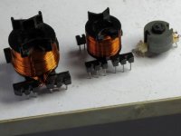
I went on to prototype a couple of air-cored inductors. They do turn out much larger than the P14 cores (no big surprises there) and lower Q. I haven't settled on a core size yet - I started with PQ20 and then PQ26 and neither could reach my target Q. Its looking at present like PQ32 will give the lowest acceptable Q. The wire probably needs to be multistrand or even litz to get around proximity effect. I'll continue more experiments today.
Here's a shot of my first two attempts at winding - the P14 core is on the right, in the middle is PQ20 and to the left, PQ26.
Measurements like dynamic range are tricky because I don't have a way to measure noise. I can show it in FFT but it needs software to add all FFT bins together to get a number. Crosstalk should be fairly straightforward though, I'll look into it. IMD I prefer to do as a multi-tone, again possible.
Back to the topic of air-cored inductors, I've been doing one or two experiments to see how practical it is. I ran a simulation with the Q of my existing inductors reduced by a factor of 4 just to see how it would affect the FR. It turns out that with some capacitor tweaks the passband ripple is reduced but the stopband rejection suffers somewhat. Not badly enough to abandon the experiment though.
I went on to prototype a couple of air-cored inductors. They do turn out much larger than the P14 cores (no big surprises there) and lower Q. I haven't settled on a core size yet - I started with PQ20 and then PQ26 and neither could reach my target Q. Its looking at present like PQ32 will give the lowest acceptable Q. The wire probably needs to be multistrand or even litz to get around proximity effect. I'll continue more experiments today.
Here's a shot of my first two attempts at winding - the P14 core is on the right, in the middle is PQ20 and to the left, PQ26.
Attachments
Last edited:
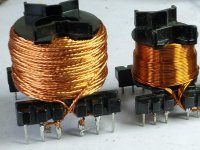
The PQ32 inductor exceeds the target spec, its not a trivial one to make though. I twisted four strands of 0.31mm wire together and made a copper 'rope' to wind it with. I'm limited to how much rope I can make in one length though (about 10m) - this one needed about 13m hence two sections I joined.
It reads 505uH from 192 turns and the DCR is 0.9ohm. AC resistance @20kHz is 1.4ohm giving a Q of almost 47. The P14 ferrite cored coil has Q ~145 for comparison.
The PQ32 bloated looking beast is the one on the left, next to the rather diminutive PQ26 on the right.
It reads 505uH from 192 turns and the DCR is 0.9ohm. AC resistance @20kHz is 1.4ohm giving a Q of almost 47. The P14 ferrite cored coil has Q ~145 for comparison.
The PQ32 bloated looking beast is the one on the left, next to the rather diminutive PQ26 on the right.
Attachments
Last edited:
The PQ32 inductor exceeds the target spec, its not a trivial one to make though. I twisted four strands of 0.31mm wire together and made a copper 'rope' to wind it with. I'm limited to how much rope I can make in one length though (about 10m) - this one needed about 13m hence two sections I joined.
That’s good news.
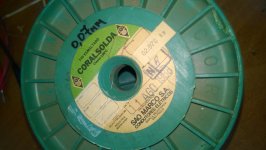
I have a big bobbin of (NOS 😀 ) much thinner enameled wire. I guess I will have to wind the coil in four sections.
When I had wound the output coils of the class D Truepath amp kit, the self-made 8strand wire made a good audible difference compared to the supplied 2strands wire.
George
Attachments
George - are you seriously thinking of building an air-cored filter for your PhiDAC hex? Recall I'm sending the usual ferrite cores with yours along with enough 0.33mm wire for you to wind them yourself - which is about 10m.
P.S. I hope that 0.07mm wire in your picture isn't enamelled, it'll be a complete b*gg*r to strip!
P.S. I hope that 0.07mm wire in your picture isn't enamelled, it'll be a complete b*gg*r to strip!
seriously thinking of building an air-cored filter for your PhiDAC hex
Don’t give me ideas 😀
No I’ ll wind over the ferrite core.
I can do comparisons btn the 0.33mm wire ferrite and the multistrand wire ferrite then.
Yes, the 0.07mm wire is enameled, otherwise twisted multistranding doesn’t provide any HF benefit.
This thin, still is manageable to strip (I ‘ve tried thinner @#&* wire)
George
Oh, I was only referring to the kind of insulation, not presence/absence of it. All the thinner wire (say under 0.2mm) I buy nowadays with the self-fluxing coating so it just has to be soldered (for a longish time) to melt it. I still have some older 0.12mm wire and getting the enamel off that without breaking it is frustratingly difficult. I can't imagine 0.07mm with real enamelling.😱
Oh, I see.
I wasn’t aware of the modern conveniences.
I use high grit sandpaper. 220 is fine for this wire
George
I wasn’t aware of the modern conveniences.
I use high grit sandpaper. 220 is fine for this wire
George
Now I have 3 inductors with high enough Q - the next challenge is how to arrange them so they barely couple to each other. Or so that they couple in a very predictable manner so that the filter can be designed around that coupling. LTspice is useful here as the coupling coefficient (K) between inductors can be input as a parameter. The tricky bit though is knowing how much physical separation corresponds to how large a value of K. So I experimented with a signal generator and AC voltmeter.
The lowest coupling between two inductors is when their axes of winding are orthogonal. I wonder if that principle extends from two to three inductors - will we still get minimal coupling so long as all axes are at right angles to one another? If so then the fundamental nature of 3D space would seem to indicate I can't place a 4th (or further) inductor in such a way as to minimize coupling with the 3 already there. Which becomes a hint that this should just be a mono filter....
The lowest coupling between two inductors is when their axes of winding are orthogonal. I wonder if that principle extends from two to three inductors - will we still get minimal coupling so long as all axes are at right angles to one another? If so then the fundamental nature of 3D space would seem to indicate I can't place a 4th (or further) inductor in such a way as to minimize coupling with the 3 already there. Which becomes a hint that this should just be a mono filter....
Attachments
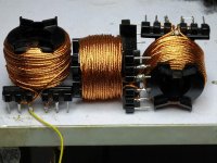
As a first approach, it seems the proper orientation for limited distance btn the coils.
What is the frequency spectrum of the signal at the output of the DAC that has to be LP filtered? I would start from there.
I would use a HF signal generator to feed the filters, a sniffer coil to probe the field of the coils and start doing some measurements.
Then I would use music and record with the soundcard the output of the DAC/filter assy. I would compare recordings made during the mods in filter design.
George
Any update on air core inductors? Will you complete a 2 channels filter with those ones then make listening tests? I guess other members are curious like me.
- Home
- Source & Line
- Digital Line Level
- lingDAC - cost effective RBCD multibit DAC design