😕 Damn, I messed track 5 up. These are not vinyl but Flac files (CD rips).Are these ripped vinyl?
T5 seem to be different tracks?
//
I can redo 5. I chose that one because it is a 40 voice choral piece. Lesser dacs can't resolve that so well.
If anyone has a favorite song they know well and want to hear it A/B, let me know.
Phase inversion test
Here is another interesting test.
Dropbox - Phase Inversion.flac - Simplify your life
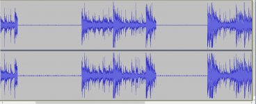
I took an Original Phidac and a Quad and aligned them in Reaper. Then I phase inverted one track. This cancels out all audio that is the same and leaves only what is different. What is curious is that there is more "different" information in the right channel than the left. Here is also a visual of this recording.
I provided the audio sample in the link above.

This is post #93 from 2018. Ironically this is second time that I see phase linearity as a goal here even though audio quality is the main interest in whole site. Other one was jbau's analog power supply experiment based on LT1085/LM337 (circuit schematic a few post below). According to his experiments, more phase linear power supply in audio band, more detail and holographic presentation attained.
There's a lot to read in that thread, I skimmed a bit to get a flavour of what jbau was doing there. Phase linearity of power supplies is rather a different thing from phase linearity of signal. He's powering opamps which as far as I could see don't run in SE classA like mine do in PhiDAC hex. The reason for running SE classA is to minimize the effect on SQ of power supplies - jbau's approach looked to be the complementary one. That is : given normal classAB opamps, what's the best power supply? I took that approach in PhiDAC SE. I reckon addressing the power-sensitivity of the circuit gives better results but anyone can have a listen to PhiDAC hex vs PhiDAC SE and make up their own mind 🙂
Reading on, a bit later I see @KSTR has already come to the same conclusion as me. From post #166 he says :
A way of improving rail exitation spectra is by forcing class-A operation and when you use balanced circuits the net draw from the PSU is constant. This can also be done in single-ended by adding dummies (not part of the signal chain) for the sole purpose of getting that constant current draw action (very feasible and very effective, too, with dual opamps like good ol' 5532's and the like) -- together with a reasonably clean and flat impedance supply and proper local bypassing this IME does more good than a better supply with an amp stage design not drawing as constant a current as possible.
Last edited:
😕 Damn, I messed track 5 up. These are not vinyl but Flac files (CD rips).
I can redo 5. I chose that one because it is a 40 voice choral piece. Lesser dacs can't resolve that so well.
If anyone has a favorite song they know well and want to hear it A/B, let me know.
Please use these (also) so that we can have a known reference?
http://www.lindberg.no/hires/test/2L-109_05_stereo-44k-16b.flac
http://www.lindberg.no/hires/test/2L-056_03_stereo-44kHz-16b.flac
http://www.lindberg.no/hires/test/2L-110_04_stereo-44k-16b.flac
What is your A/D?
//
Last edited:
Here are those songs to compare.
Dropbox - New Test - Simplify your life
The folder includes the originals and the names are prefixed with Q1 for original Phidac and Q4 for the quad.
Also track 5 of the first test has been corrected.
As for the signal chain for recording: Foobar 2000 > usb to spdif (sa9023) > AK4118 I2S > Phidac > Headphone amp > ALC898 line in on pc
Thanks - beware to redistribute those files - probably a copyright infringement!?
//
These tracks are from a free sampler. I assume they are ok?
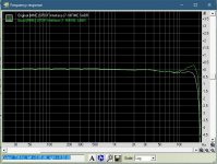
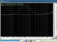
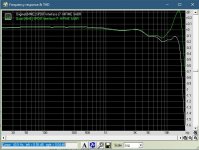
The FR change could be because the quad is taking those tiny 0805 inductors much closer to their working limits. Likely the inductance is going to change with current through them which will tweak the FR.
Measurements are interesting but not indicative of how a human enjoys music. While my es9018 measures better it does not have the absorbing presentation of either of these Phidacs. There is something that measurements don’t capture.
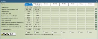
Are these numbers represent real world measurements of PhiDAC? Is there any sensible explanation of deviation from datasheet specs?
If someone can explain to me how to make sure I am setting it up correctly I can remeasure. This was my first time using RMAA so I assume it is my error.Are these numbers represent real world measurements of PhiDAC? Is there any sensible explanation of deviation from datasheet specs?
Schematic for the kits
I hesitate to say this is the final schematic for PhiDAC hex but its the one I'm using to create the kits from. Stay tuned!
Incidentally for the 0805 resistors and capacitors in the kits there's always one added in case you drop one into your thick pile carpet and don't want to spend hours tracking it down. But there is just one extra for each value - any losses beyond that will be your own responsibility 😱 On the AD829 and AD744 because I've experienced very occasional dodgy ones, I'm including one spare of each. AD815 I've not experienced failed ones out of the tube, so no spare there. The particular batch of DAC chips I'm using, also I haven't experienced a failure.
Attachments
Hi Richard, thanks for the update on the final schematics. Can you shed some more color on the difference between the 3rd order vs the 7th filter kit....it will help me and probably others to choose. thanks
Sure - neither of these filters is a textbook filter for a non-oversampling DAC. To do anti-imaging filtering by the book would probably need a filter with 6 inductors per channel. Therefore both filters are a practical compromise in a way - the 7th order filter gives more than 60dB of rejection of DAC images but only from 27kHz and up, meaning recorded frequencies above 17kHz will have poorer than 60dB rejection of images. Such a steep filter comes at the cost of some post-ringing which you can see in post #781, left plot.
The 3rd order filter has a much gentler slope, less post-ringing (post #781, right plot) but doesn't do much to suppress images at higher frequencies. Hence an 18kHz sinewave doesn't look very much sine-shaped, as you can see in post #794, left plot.
Subjectively there's no doubt I prefer the 7th order filter, my wife does too and she's less likely swayed by confirmation bias than I am.
Just a little footnote - as far as I'm aware, no other commercially available NOS DAC has even a 3rd order filter though I think Pedja Rogic's designs might have a 2nd order one (do please correct me if I've gotten this wrong). Your typical commercial NOS DAC has an RC filter which means a 1st order one. Which is why you'll often see pictures of 'stair steps' coming out of them.
Last edited:
I don't want to see waveforms, I want to hear it... I would order my kit straight away, but unfortunately my private courier is locked down. If you get any interest from RSA, please let me know. You will never see my posts anymore, I promise. .kidding.
What equipment do you use for listening tests, @abraxalito?
What equipment do you use for listening tests, @abraxalito?
Clarification about DAC kits
Yesterday I received a PM asking about kits for the filters. Rather than reply to that, I decided its better to give a public response to clear up any remaining misunderstandings. There will be no kits for the filters.
The reason for there being no kits for filters is relatively simple - there's too much work involved in selecting parts - inductors and capacitors - for them to make a kit economical. I have many reels of caps and inductors here of various values, I need to select caps and inductors off the reels by value (using my trusty LCR meter) and bin them. Thus they're unpackaged and more tricky to handle. When time comes to build a filter I select the caps and inductors to suit the filter. On the 3rd order filter some inductors won't ever be suitable because their value is too high. The cap values are in some cases made up of 4 caps in parallel to get close enough to the target capacitance - I aim to do better than 1%, normally I get to 0.5%.
If anyone wants to DIY their own filter then I'll sell you a bare PCB when you buy a kit for the mainboard, price is $1 (7RMB). You can buy 1% NP0 capacitors from Mouser, the 100nF are about $1 each, you need 14 of them plus an assortment of smaller values to complete the 7th order filter. The cores aren't available from either Mouser or Digikey but Digikey does have electrically similar cores (P14 size in the right material with AL=160) - just the footprints aren't mechanically compatible with my PCB. A set of 6 cores - you need to order various line items, bobbins, cores, bases etc. - will cost in the region of $50. Then you need magnet wire, about $9 for a reel if I remember correctly. You'll also need an inductance meter (1% or better accuracy preferably) to check your wound and assembled cores have the target values.
DIYing the 3rd order filter is possible but you would likely need to order a few dozen TDK SLF7045 inductors to be sure to get pairs close enough to the target values as the tolerance is +/-20%.
If any of the above causes anyone to have further questions, do please ask.
@sajunky I'm not expecting an order from you as you have said on the Denafrips thread :
Watch my lips - our hearing is subjective.
Yesterday I received a PM asking about kits for the filters. Rather than reply to that, I decided its better to give a public response to clear up any remaining misunderstandings. There will be no kits for the filters.
The reason for there being no kits for filters is relatively simple - there's too much work involved in selecting parts - inductors and capacitors - for them to make a kit economical. I have many reels of caps and inductors here of various values, I need to select caps and inductors off the reels by value (using my trusty LCR meter) and bin them. Thus they're unpackaged and more tricky to handle. When time comes to build a filter I select the caps and inductors to suit the filter. On the 3rd order filter some inductors won't ever be suitable because their value is too high. The cap values are in some cases made up of 4 caps in parallel to get close enough to the target capacitance - I aim to do better than 1%, normally I get to 0.5%.
If anyone wants to DIY their own filter then I'll sell you a bare PCB when you buy a kit for the mainboard, price is $1 (7RMB). You can buy 1% NP0 capacitors from Mouser, the 100nF are about $1 each, you need 14 of them plus an assortment of smaller values to complete the 7th order filter. The cores aren't available from either Mouser or Digikey but Digikey does have electrically similar cores (P14 size in the right material with AL=160) - just the footprints aren't mechanically compatible with my PCB. A set of 6 cores - you need to order various line items, bobbins, cores, bases etc. - will cost in the region of $50. Then you need magnet wire, about $9 for a reel if I remember correctly. You'll also need an inductance meter (1% or better accuracy preferably) to check your wound and assembled cores have the target values.
DIYing the 3rd order filter is possible but you would likely need to order a few dozen TDK SLF7045 inductors to be sure to get pairs close enough to the target values as the tolerance is +/-20%.
If any of the above causes anyone to have further questions, do please ask.
@sajunky I'm not expecting an order from you as you have said on the Denafrips thread :
sajunky said:Personally I will never buy a product from a designer who claims that our hearing is subjective.
Watch my lips - our hearing is subjective.
When I asked about kits, I didn't refer the filter circuit specifically but whole unpopulated kit with mainboard. By the way, since you have already gave a quote for populated and tested kits, I was expecting additional quote for unpopulated kits since you have impiied that below if I understand correctly.
I hesitate to say this is the final schematic for PhiDAC hex but its the one I'm using to create the kits from. Stay tuned!
Incidentally for the 0805 resistors and capacitors in the kits there's always one added in case you drop one into your thick pile carpet and don't want to spend hours tracking it down. But there is just one extra for each value - any losses beyond that will be your own responsibility 😱 On the AD829 and AD744 because I've experienced very occasional dodgy ones, I'm including one spare of each. AD815 I've not experienced failed ones out of the tube, so no spare there. The particular batch of DAC chips I'm using, also I haven't experienced a failure.
I'm still not following what you're asking here. To my way of thinking there can be no 'populated and tested kit' - if its populated and tested, its not a kit at all rather a built up DAC assembly. Filters are all populated and tested, mainboards are not.
I'm still not following what you're asking here. To my way of thinking there can be no 'populated and tested kit' - if its populated and tested, its not a kit at all rather a built up DAC assembly. Filters are all populated and tested, mainboards are not.
Ok, that was my misunderstanding then.
- Home
- Source & Line
- Digital Line Level
- lingDAC - cost effective RBCD multibit DAC design
