You are right as for a sufficient rejection of images, @abraxalito. Nothing is wrong in your approach, keep a good work. If any doubts, Foobar2000 with SoX is giving free upsampling. With upsampling 44.1KHz source twice, we don't have to worry about imaging anymore. Most of the music I download now has a higher sampling rate anyway.
As for the preference of a digital filter brick wall, it is personal. It gives flexibility to the design, better measurements, but sonic advantage is at least questionable. When chosing between brick wall filter and upsampling, I will always do quality upsampling on a fast PC CPU.
At the moment I do enjoy a second-hand Audio GD R2R-11, I was lucky to buy locally. I got it only because of GrossDAC project delay, first a flu in China and now a complete lockdown of South Africa. I wouldn't be able to order anyhing during 21 days, while (more realistic) it will be extended to three months.
A-GD R2R-11 is a NOS design. I don't see any second-order LP filters, it would be some inductors in this no-feedback amp design. I don't see any, but it sounds fabulous, very real and natural presentation.
Last edited:
Good question - the spec says 2% (mid ranges) but I will compare mine with my dedicated LCR meter and see if its any better than that in practice.
Since the PCBs are now in I've started building the first filter board and compared the capacitance readings I get on my LCR meter with those from the ZT219. They're reassuringly close - the ZT219 being about 0.2% away from the LCR. Which is plenty good enough in this application. But of course this is just my meter, no guarantees about anyone else's.
I'm not sure if 2% is good enough yet as I always aim to get better than 1% for my capacitance values. It would depend on how much passband ripple you think is acceptable - the kinks in the response which are just visible on the plots in post #716 will get bigger. But they're pretty small in comparison with the usual kinks in speaker response plots so I'm not sure they'll be audible.
Oh I noticed that the excellent accuracy of my meter doesn't extend to the lowest capacitance range (9.999nF) - on that range there seems to be an offset caused by some stray capacitance which isn't being nulled out. So it consistently reads higher than my LCR meter.
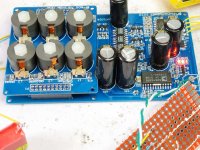
I'm pleased to report I have now gotten the first prototype singing. I found my first suspect AD829 in this build having soldered down a few dozen already. I may have to change one of the red LEDs to an IR LED to get the reference voltage into the right region, its at present too high with 3 red ones. I also need to figure out a way to make debugging a bit easier - with the filter in place the analog parts are too hard to probe. Some test points on the bottom might resolve this. Now to build up a few more and try a few tweaks.....
Oh I noticed that the excellent accuracy of my meter doesn't extend to the lowest capacitance range (9.999nF) - on that range there seems to be an offset caused by some stray capacitance which isn't being nulled out. So it consistently reads higher than my LCR meter.
I'm pleased to report I have now gotten the first prototype singing. I found my first suspect AD829 in this build having soldered down a few dozen already. I may have to change one of the red LEDs to an IR LED to get the reference voltage into the right region, its at present too high with 3 red ones. I also need to figure out a way to make debugging a bit easier - with the filter in place the analog parts are too hard to probe. Some test points on the bottom might resolve this. Now to build up a few more and try a few tweaks.....
Attachments
Hey Richard, I was gone for 2 weeks of insanity and you have been busy! This implementation does not look like it has as many capacitors, no hats, no pants etc..
How does it sound compared to the Phidac and the original Lingdac?
Also, when you are happy with the layout and have it finalized, put me down for 5 boards.
How does it sound compared to the Phidac and the original Lingdac?
Also, when you are happy with the layout and have it finalized, put me down for 5 boards.
Hi Luke
Happy to talk you through the stages of the design, then if you have any detailed questions I'll have a go at answering them.
I2S inputs come in to U4 which buffers them so the outputs are 0-2.5V. The signals are then level shifted as the DAC chips 0V pins aren't at circuit ground. Level shifting is done by running constant current (from Q1-Q7 ex Q4) sources through resistors (R56,R65,R7) which act as floating voltage sources thus adding about 3V to each signal.
Output from the 4 paralleled DAC chips is paralleled and fed into the LC filter which is on a daughter board. This filter implements a sharp cut-off frequency around 18kHz and rejects by 60dB or so all frequencies above 27kHz. Its output is loaded by R29 (for L channel) and then into an I/V converter which is U2. External PNP transistors form its output stage, bypassing the internal one. The final stage of the DAC is a 3rd order MFB (multi-feedback) low-pass filter which gives a boost to higher frequencies (approx 3dB at 18kHz) to counteract the 'NOS droop'. That's built out of U3 (AD744) which also has a classA external OPS made from discrete PNP transistors. The idea of these discrete OPSs is they draw a constant current from the positive supply and hence don't create supply noise which is correlated with the signal as classAB OPSs do.
Power supplies for the DAC chips and opamps are created by the AD815 which uses as its reference the string of 3 red LEDs to give around 5V.
Overall the design is the same as the original PhiDAC in architecture, just some different implementation details.
thanks for the explanation abraxalito, It was confusing because I thought that P1-P4 were chips, i think they are are a connector. I also didn't know why there was a filter at the output, never heard of NOS droop, do all NOS dacs suffer this?
I have listened to parralel ad1955 and didn't like it as much as a single, however I don't really like this dac chip so much. I also didn't think parallel tda1543 was that good, but this is not a high res chip, musical and nice sounding, but misses alot of the detail.
@stellarelephant - good to see you again on the thread Kevin. Yeah the larger board saves time in interconnection even though the form factor doesn't look quite as cute. The industrial-looking filter might turn out to be overkill, we shall see
@pelopidas I sure have been busy but that's for a good reason - not much else to do when everywhere outside goes into 'suspended animation' ! You don't reckon the filter-on-top counts as a 'hat' ? But no pants this time as that nut is cracked in a different way. As for sound, its clearer and with more 'air' than the PhiDAC. I've not listened to lingDAC in such a long time I can't come up with a direct comparison but I would guess it beats that in the bass, lingDAC's was a bit on the weak side with its stock PSU. A comparison of the HF of the two would be interesting. Thanks for your reserve order
@Luke All NOS DACs suffer from NOS droop yes, its baked into the math. I started my DAC journey with AD1955, I wonder if any of my original modded boards are still serviceable...
At the start of my DAC journey I really didn't have any reference other than comparing a modded board to the original. I did find mods made a surprising amount of difference, mainly because the layout initially was so bad (the designer had ignored DS recommendations). I played around a lot with opamp I/V stages and filtering but eventually migrated to playing with TDA1543s which initially sounded rather dull to me in comparison. Is that what you meant by 'lacked detail' ?
You'll then need at the very least a headphone amp to create the simplest system - I am working on a design for that or you could use the SEbuff from lingDAC which is earlier in the thread.
Hello Richard,
(with reference to the above quote from post #709), would the SEbuff require modifictions in this case?
And if one's system comprises a preamplifier + amplifier, is the SEbuff still necessary to interface the PhiDAC/LingDAC (to the system)?
Hello abraxilito,
I recall the lingdac v2 design had space for non fit capacitors with regard to compensating variation of inductors and their effects to frequency response. The difficulty to non technical eventually led to the abandonment of the lingdac, however those with understanding can still progress.
The lack of base had also arisen from some in the lingdac, although I can’t say that I found/find that (simple battery power). The power supply improvement from subsequent development has led to better low frequency.
Is there any way to make improvements to the existing lingdac power supply? Or is it best just to move along with the new progress?
(with reference to the above quote from post #709), would the SEbuff require modifictions in this case?
No mods required to the SEbuff but it runs at 7V so will need a regulator to reduce the 12V supplied to the DAC. Alternatively if the headphones being driven were higher impedance ones (say HD650 300R) then the SEbuff could be driven direct from 12V and the bias current reduced to maintain the same dissipation in the FETs.
And if one's system comprises a preamplifier + amplifier, is the SEbuff still necessary to interface the PhiDAC/LingDAC (to the system)?
No need for SEbuff if the load to be driven is a normal line-level one (above 5k say). The buffer's only needed to drive headphones i.e. high current loads.
The lack of base had also arisen from some in the lingdac, although I can’t say that I found/find that (simple battery power). The power supply improvement from subsequent development has led to better low frequency.
Running on batteries - low impedance LiFePO4 would be ideal - wasn't the configuration when I remarked on the bass weakness of lingDAC. Rather I was running with the stock PSU board which has a few switched-cap voltage doublers and discrete series regs. Adding extra caps on the supply to the filter-I/V board improved matters in the bass with that set-up.
Is there any way to make improvements to the existing lingdac power supply? Or is it best just to move along with the new progress?
Run the filter-I/V board on the lowest impedance supply you can get, either with low ESR batteries or lots and lots of caps. I think I ran with over 100,000uF in my improved set-up - I discovered that my substantial supply of Panasonic 15,000uF 6.3V caps still worked fine at 9V
At the start of my DAC journey I really didn't have any reference other than comparing a modded board to the original. I did find mods made a surprising amount of difference, mainly because the layout initially was so bad (the designer had ignored DS recommendations). I played around a lot with opamp I/V stages and filtering but eventually migrated to playing with TDA1543s which initially sounded rather dull to me in comparison. Is that what you meant by 'lacked detail' ?
Yes dull is a fair comparison to make against the AD1955.
I eventually discovered that relative 'dullness' was more true to the source than the 'detail' which I had become accustomed to in AD1955. That finding was made when I started playing with low-pass filtering on the output of a DAC - by increasing the number of ferrite beads I used between DAC and I/V stage I was able to reduce the amount of 'detail' I got. Now I see 'detail' as an artifact which indicates something wrong in the DAC.
Of course some of the 'dullness' comes as a result of NOS droop so that needs fixing up.
Of course some of the 'dullness' comes as a result of NOS droop so that needs fixing up.
that's an interesting observation regarding detail being filtered out. I have a buffalo dac and a TDA1541 OS dac (pedja) and they both sound better to me. than tda1543 or AD1955, my biggest problem is my speakers are not good as the rest of my audio (kef Q900). I want to upgrade them at some stage, but they aren't too bad either.
No mods required to the SEbuff but it runs at 7V so will need a regulator to reduce the 12V supplied to the DAC. Alternatively if the headphones being driven were higher impedance ones (say HD650 300R) then the SEbuff could be driven direct from 12V and the bias current reduced to maintain the same dissipation in the FETs.
No need for SEbuff if the load to be driven is a normal line-level one (above 5k say). The buffer's only needed to drive headphones i.e. high current loads.
Ok thanks !
- Home
- Source & Line
- Digital Line Level
- lingDAC - cost effective RBCD multibit DAC design