If one thinks about the resistor element switching in ES9038Q2M, it should be apparent that the best it could do is send current to the I/V opamp and or to send current to ground, say, a mix of the two in some varying proportion such that the current sum is always constant. However, those two current paths may have different enough behaviors and different enough ground return paths to have some effect as seen by the AVCC regulator. May affect how the regulator needs to dynamically respond. When I say, 'may' that means I don't know. Haven't tried to find out, but I suspect there is going to be something to regulate.
What I believe is if it were so simple as that there were really constant current draw then putting a resistor between AVCC and the regulator output should have no audible or measurable effect (except for the added resistor noise, and a constant drop in audio output volume level). That's because the voltage drop across the resistor would be constant, so AVCC voltage would be constant too. Someone want to try it?
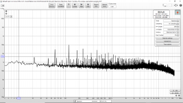
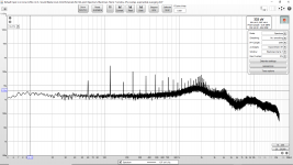
I did some noise measurements on the AVCC-R today.
Attached are:
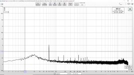
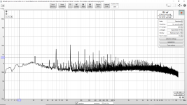
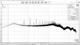
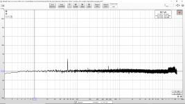
First: AVCC-R with DAC powered down.
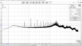
Second: AVCC-R with DAC powered on but idle.
First: AVCC-R with DAC powered on with 1kHz full scale on right channel.
Interestingly I don't really see a 1kHz spur.
Any chance you can repeat such measurements with your recommended AVCC supply? I would like to see measurements of the recommended/more expensive/more involved changes.
I think I can improve my measurements further. The 60 dB LNA is well shielded. But I need to find a larger outer shielding so that the DAC and probe cable can be shielded better.
Attachments
Not sure how meaningful that is. Maybe more interesting to look at AVCC current, or both voltage and current. Or, maybe try AVCC voltage verses dac board analog output noise.
That said, it all seems a bit academic at this point. We already know the AVCC supply needs some serious work.
That said, it all seems a bit academic at this point. We already know the AVCC supply needs some serious work.
Last edited:
That said, it all seems a bit of academic at this point. We already know the AVCC supply needs some serious work.
But the question is what is the noise level with the various proposed changes? Is it better than what I am reading? If so how? Are there less or lower spurs? Or is the baseline noise level lower?
Did anyone measure noise before and after making the proposed changes on the recommended board?
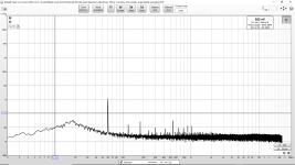
I did some noise measurements on VCCA.
Attached are:
Attached are:
First: With DAC powered down.
Second: With DAC powered on but idle.
First: With DAC powered on with 1kHz full scale on right channel.
I would like to compare these with any measure done before and after the proposed changes on the recommended board. If anyone has that data please post it.Second: With DAC powered on but idle.
First: With DAC powered on with 1kHz full scale on right channel.
Attachments
BTW guys. most of mouser's stock is gone, with no new delivery from ESS for 16 weeks .... guess i'm back to dealing with ESS direct. That being said; I got quite a fast response a couple weeks ago; as I want some of the 4 channel PRO ADC; which was for some reason not listed at mouser.
there are no ES9038PRO and last night there was only 4 x 9038q2m left.
there are no ES9038PRO and last night there was only 4 x 9038q2m left.
I did some noise measurements on the AVCC-R today.
was there a resistor in series with regulator?
measuring the drop across the resistor at load could be interesting at different signal frequencies. even small current changes can show. 10R should do it. it is much larger than the resistance of any decent regulator. also, any good size capacitor after the resistor would likely mitigate the value of the measurement. but the drop across isn't meaningful in itself. Distortion with and without a resistor in series is, to know if regulator output impedance is more meaningful, i would assume.
Last edited:
I am interested in seeing the noise levels at stock, with my modifications and with the proposed modifications. The premise that was presented can be summarized as: AVCC is very sensitive and needs ultra-low noise and a very high PSRR regulator.
I would like to see data. Has anyone measured noise at this pin?
I have not placed a resistor in series with the regulator for AVCC-R measurements. ESS recommended (for the power up sequence) that AVCC power up last. If I remove all the bypassing from AVCC (so that I can place a series resistor) it will not power up last. Also there would be an enormous amount of additional noise. I am not sure this is a good idea. I am not even sure if the DAC would be damaged?
What do you hope to gain from such a measurement?
I am not sure I want to cut the tiny trace between the bypass and the AVCC-R pin to insert a resistor. The trace near the pin is tiny. (It is thin and short. Maybe 2mm length from the last (ceramic) bypass. The QFN is tiny to work around.)
Could someone with the recommended LME49720/LM4562 AVCC-R supply measure and post the noise at the pin?
kozard,
Why are you measuring VCCA? You want to check the RF analog rail too?
Why don't you just measure the shared 3.3v rail that everything uses? Might give you an idea of where a number of problems arise.
Regarding you questions re measurements, I don't think anybody measured them. First of all, it would probably be wise to measure various rails with a wide bandwidth scope first using an active differential probe. Then you get good view of the big picture.
Then to work back in the other direction, measure an FFT at the audio output of the dac board. Introduce a signal, say, at AVCC using a signal generator, maybe cap coupled and through a current limiting resistor. See if you can figure out how much test signal can be tolerated at AVCC without affecting the dac board output. Isn't that what you really need to know? You could do it with or without the caps. With some more thought and depending on the test signal source there is probably some way to get a good handle on injected signal level at AVCC without having to look at all that other noise garbage maybe coming in from the shared 3.3v rail and or from stray coupling.
Last edited:
kozard,
Why are you measuring VCCA?
One reason is that I want to see where certain noise and spurs originate. Thus I am looking at each pin and then the supply buss, as well as the input to the regulator. If I can pinpoint and cleanup the largest generators of noise that should help the most sensitive pins. I also I want to see which regulator and bypass scheme results in the least noise at the sensitive pins.
You want to check the RF analog rail too?
What are you referring to as the RF analog rail?
Why don't you just measure the shared 3.3v rail that everything uses? Might give you an idea of where a number of problems arise.
I am. I just measured the input to the 3.3V rail. It takes time to do these measurements. Which points would you measure?
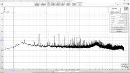
I did some noise measurements on the input to the 3.3V regulator.
Attached are:
Attached are:
First: With DAC powered down.
Second: With DAC powered on but idle.
First: With DAC powered on with 1kHz full scale on right channel.
I would like to compare these with any measure done before and after the proposed changes on the recommended board. If anyone has that data please post it.Second: With DAC powered on but idle.
First: With DAC powered on with 1kHz full scale on right channel.
Attachments
VCCA is the analog RF system rail for the dac chip, its for clocking and related stuff. The 3.3v digital rail is DVCC. The output resistor rails are AVCC_L and AVCC_R. There is a another lower voltage digital rail in ES9038Q2M but it has an internal regulator, so it only requires external decoupling.
Okay, you have a lot of power line harmonic spurs. Why don't you fix that first?
Thing is if you fix each power rail to better than your sound card can measure, the dac will sound better. If you do the big things that have the most effect first then it will be easier to appreciate the more subtle improvements for each remaining thing that is fixed. The result will be when everything is fixed to better than your sound card can measure, the dac will sound best. No problem with you doing whatever you want to do, but I have my doubts about some of the ultimate usefulness.
Thing is if you fix each power rail to better than your sound card can measure, the dac will sound better. If you do the big things that have the most effect first then it will be easier to appreciate the more subtle improvements for each remaining thing that is fixed. The result will be when everything is fixed to better than your sound card can measure, the dac will sound best. No problem with you doing whatever you want to do, but I have my doubts about some of the ultimate usefulness.
Last edited:
VCCA is the analog RF system rail for the dac chip, its for clocking and related stuff. The 3.3v digital rail is DVCC. The output resistor rails are AVCC_L and AVCC_R. There is a another lower voltage digital rail in ES9038Q2M but it has an internal regulator, so it only requires external decoupling.
Post 6724 (yesterday) was VCCA. Data says "3.3V Analog Supply for OSC" so I guess RF system rail.
I was not planning on probing the 1.2V rail. (DVDD, pin 15.)
Okay, you have a lot of power line harmonic spurs. Why don't you fix that first?
Would like to. The main one is 60Hz. 120Hz is much lower. So likely the whole setup needs better magnetic shielding. To get the 60Hz down on the LNA I put it in a steel tin and then put the steel tin in a heavy steel pot.
With the recommended changes from post 3003 what do you think the noise looks like on AVCC_L?
What about 180Hz? 240Hz? Where are those coming from?
Regarding the noise improvement to AVCC from the circuit in post #3003. A whole lot depends on layout and stray coupling from remaining noise sources. If you take care of all those things properly, and if you clean up your measurement setup more, then you might see a very, very slight modulation on AVCC from the audio being played. However it may not be new harmonics. It might be random spikes of HF/RF switching noise. It may just be a very tiny version of the audio signal being played. Might be some combination of those types of things. Depends on actual current draw from AVCC and gain of opamp buffer error amplifiers. They are trying to regulate the voltage but have finite gain available with which to do it. Basic idea anyway. Stray coupling and power quality for opamps are examples of some types of things that could make it hard to get as close as we might like to ideal behavior.
Regarding the noise improvement to AVCC from the circuit in post #3003. A whole lot depends on layout and stray coupling from remaining noise sources. If you take care of all those things properly, and if you clean up your measurement setup more, then you might see a very, very slight modulation on AVCC from the audio being played. However it may not be new harmonics. It might be random spikes of HF/RF switching noise. It may just be a very tiny version of the audio signal being played. Might be some combination of those types of things. Depends on actual current draw from AVCC and gain of opamp buffer error amplifiers. They are trying to regulate the voltage but have finite gain available with which to do it. Basic idea anyway. Stray coupling and power quality for opamps are examples of some types of things that could make it hard to get as close as we might like to ideal behavior.
Last edited:
How are you going to evaluate the benefit of each change/improvement you make to a rail, by FFT spur changes only?
No. You have seen my posts with measurements of the DAC and also you have seen my posts about listening to the DAC including comments on how I compare between two.
What about 180Hz? 240Hz? Where are those coming from?
I need to do some experiments to figure out how to reduce them. At that point (input to the 3.3V regulator) there are already two regulators. (The input to the 7805 is already regulated.)
How are you going to evaluate the benefit of each change/improvement you make to a rail, by FFT spur changes only?
Did you evaluate the recommended supply changes with measurements and data on the supplies? Can you post the data?
Seriously, if people are going to go on about ultra low noise regulators, PSRR and the need for film capacitors on power supplies are you really surprised that someone would go and try to measure the supplies and see what people are talking about? If ultra low noise and high PSRR is needed doesn't the standard approach include measurements?
Last edited:
If ultra low noise and high PSRR is needed doesn't the standard approach include measurements?
Normally yes, but apparently in this thread no

- Home
- Source & Line
- Digital Line Level
- ES9038Q2M Board