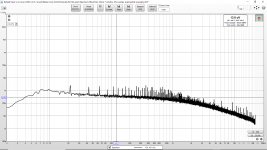
Yes, with all that Junk on the line; no chance of sorting the wheat from the chaff. thats really enormous. its like 25-35db higher than it should be. I think there are far too many variables in application to make someone elses measurements applicable to you.
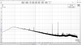
LM317 regulators with Cadj cap are in the low hundreds of nV/√Hz so the overall noise level is quite high. Also the mains related hash is too prominent. Maybe you should first try to clean that.
Yes, with all that Junk on the line; no chance of sorting the wheat from the chaff. thats really enormous. its like 25-35db higher than it should be. I think there are far too many variables in application to make someone elses measurements applicable to you.
Trying to figure that out right now.
And this is with the DAC output measuring about 30 dB improvement already. (2nd and 3rd harmonic at the limit of the ADC of my SB0490.)
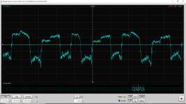
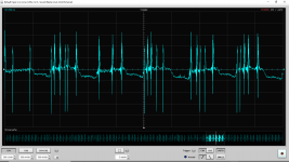
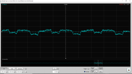
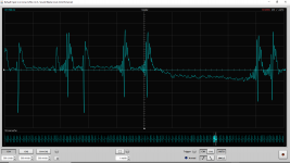
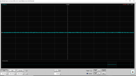
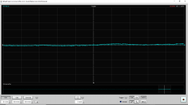
I have attached voltage waveforms from AVCC_R (powered by the stock AMS1117-3.3) and the input of the AMS1117-3.3.
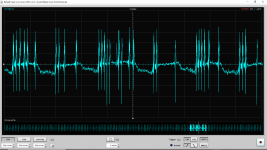
The AMS1117-3.3 input is the output of the stock LM7805 which itself is being powered by an external 9.6V regulated HPRO/Harman Pro regulated power supply for musical instrument effects processors.
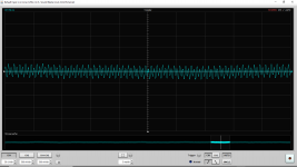
A square wave would explain all the higher harmonics...
Any ideas what is going on? Anyone have measurements to share? I would like to see what it looks like when it is working well. I am going to work on the power supply just in case the HPRO supply is outputting something ugly.
[Edited: The channel one scale is obscured in the screen capture. Not a good feature!]
Attached images in order:
The AMS1117-3.3 input is the output of the stock LM7805 which itself is being powered by an external 9.6V regulated HPRO/Harman Pro regulated power supply for musical instrument effects processors.
A square wave would explain all the higher harmonics...
Any ideas what is going on? Anyone have measurements to share? I would like to see what it looks like when it is working well. I am going to work on the power supply just in case the HPRO supply is outputting something ugly.
[Edited: The channel one scale is obscured in the screen capture. Not a good feature!]
Attached images in order:
- [100uV/Div] AVCC_R Idle
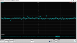
- [500uV/Div] AVCC_R 1kHz Full Scale
- [500uV/Div] AVCC_R 1kHz Full Scale Zoom In
- [500uV/Div] Regulated Input To AMS1117-3.3 Idle
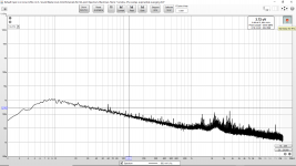
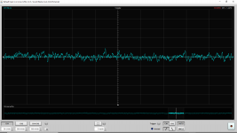
- [500uV/Div] Regulated Input To AMS1117-3.3 1kHz Full Scale
- [500uV/Div] Regulated Input To AMS1117-3.3 1kHz Full Scale Zoom In
Attachments
-
 AVCC_R Voltage_Idle.png109.2 KB · Views: 212
 -
 AVCC_R Voltage_1kHz_Full_Scale.png105.5 KB · Views: 204
 -
 AVCC_R Voltage_1kHz_Full_Scale 2.png97.9 KB · Views: 196
 -
 Input to AMS1117 Idle.png78.8 KB · Views: 205
 -
 Input to AMS1117 1kHz Full Scale.png112.5 KB · Views: 196
 -
 Input to AMS1117 1kHz Full Scale 2.png106.7 KB · Views: 135
Last edited:
Yes, with all that Junk on the line; no chance of sorting the wheat from the chaff. thats really enormous. its like 25-35db higher than it should be. I think there are far too many variables in application to make someone elses measurements applicable to you.
Not saying it would be applicable to my board. However I would love to see measurements on a very good or great ES9038Q2M example. Certain noise and spurs will come from the ES9038Q2M and it would be helpful if I knew what was "normal" in a very good or great ES9038Q2M example.
Last edited:
Could you try with battery instead of HPRO?
I am presently looking at a stack of 18650 cells and 18650 holders with that exact thought in mind. 🙂
Last edited:
People have measured power rails with an AP before. The machines can do it if there are things there that show up well on an audio FFT. RF switching spikes that might or might not cause problems might only be visible on a good scope.
There are some things an AP simply does not measure very well, but that do affect sound. There are linear distortions, and various different types of noise. Some noise and or so-called linear distortions may be time variant. Some small linear distortions may change rather slowly over time and or temperature, and some of those changes may be audible.
There are clock jitter effects, which can be quite complex in sigma-delta dacs like ES9038Q2M. One model when jitter is small enough is that the width of an FFT skirt is the convolution of clock phase noise with the audio test signal (widest down at the root, where the close-in phase noise is largest). It means clock close-in phase noise can dynamically mask small signals close in frequency to larger signal, so you can't hear the smaller signal. More discussion at: https://www.diyaudio.com/forums/dig...-reference-dac-8-channel-266.html#post6501040 ...post #2651
Moving along, there is also the matter of left/right channel timing stability relative to each other, which is also affected by clock jitter. One way we localize the lateral position of sound in front of us is by the very small differences in the time it takes the sound wave to reach each ear. Numbers in the nanosecond range are given for interaural localization sensitivity. Some more info: Sound localization - Wikipedia
So, lots of stuff that can be audible which an AP doesn't show very well. That said, if an AP shows a problem then by all means its good to try to fix the problem. Just don't mess up the other stuff that is audible in the process. Also, IMHO and IME its best not to ignore problems you can hear even if it doesn't show up on an AP.
Last edited:
People have measured power rails with an AP before. The machines can do it if there are things there that show up well on an audio FFT. RF switching spikes that might or might not cause problems might only be visible on a good scope.
There are some things an AP simply does not measure very well, but that do affect sound. There are linear distortions, and various different types of noise. Some noise and or so-called linear distortions may be time variant. Some small linear distortions may change rather slowly over time and or temperature, and some of those changes may be audible.
There are clock jitter effects, which can be quite complex in sigma-delta dacs like ES9038Q2M. One model when jitter is small enough is that the width of an FFT skirt is the convolution of clock phase noise with the test signal (widest down at the root, where the close-in phase noise is largest). It means clock close-in phase noise can dynamically mask small signals close in frequency to larger signal with noise, so you can't hear the smaller signal. More discussion at: https://www.diyaudio.com/forums/dig...-reference-dac-8-channel-266.html#post6501040 ...post #2651
Moving along, there is also the matter of left/right channel timing stability relative to each other, which is also affected by clock jitter. One way we localize the lateral position of sound in front of us is by the very small differences in the time it takes the sound wave to reach each ear. Numbers in the nanosecond range are given for interaural localization sensitivity. Some more info: Sound localization - Wikipedia
So, lots of stuff that can be audible which an AP doesn't show very well. That said, if an AP shows a problem then by all means its good to try to fix the problem. Just don't mess up the other stuff that is audible in the process. Also, IMHO and IME its best not to ignore problems you can hear even if it doesn't show up on an AP.
There is a fundamental flaw in your thinking. If the phenomen cannot be measured there is no way to make real, objective improvements. You can of course rely on your hearing when testing your tweaks but that does not necessarily mean that you are improving anything. It may well be the other way around. Our brains are different and so is our hearing, background, music taste etc. Unless you perform controlled listening tests you cannot say anything universal about your improvements. But it goes without saying that if it sounds good to you, that should be sufficient (to you).
bohrok2610,
You argue a philosophical opinion. I disagree with that opinion. I think humans can be used as test instruments and so does Sean Olive. JBL uses test panels of human listeners to evaluate speakers. They do it blind of course. The thing is that speakers are made for human enjoyment, not for measuring gravity waves. I would argue that dacs are for human enjoyment too. And I do have ways of doing very, very good listening tests, sometimes blind, but not always. Training and experience of a test panel can go a long ways towards obtaining objective results.
You argue a philosophical opinion. I disagree with that opinion. I think humans can be used as test instruments and so does Sean Olive. JBL uses test panels of human listeners to evaluate speakers. They do it blind of course. The thing is that speakers are made for human enjoyment, not for measuring gravity waves. I would argue that dacs are for human enjoyment too. And I do have ways of doing very, very good listening tests, sometimes blind, but not always. Training and experience of a test panel can go a long ways towards obtaining objective results.
Last edited:
You may have misread my post. I also said that controlled listening tests (i.e. DBTs) are fine for testing. Have you conducted DBTs regarding the various tweaks proposed in this thread? What were the results?
Of course I have. I have participated in other people's blind tests too. I once sorted unity gain noninverting audio opamps in order of distortion by ear, and did it blind. It was damn hard, but I did it.
Now I use a combination of single-blind and sighted tests because it works fine, given the listeners I use. Up to me to decide what level of scientific rigor I need to get the results I want. Its doesn't have to be a full blown publication level research study for every little listening test we do. We do use more or less the equivalent of secret balloting.
Now I use a combination of single-blind and sighted tests because it works fine, given the listeners I use. Up to me to decide what level of scientific rigor I need to get the results I want. Its doesn't have to be a full blown publication level research study for every little listening test we do. We do use more or less the equivalent of secret balloting.
Last edited:
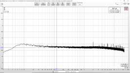
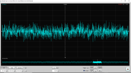
Ok. The HPRO power supply was a really bad idea. I thought a power supply for musical instrument effects processing would be pretty clean. I was wrong. The good news is that all these measurements just resulted in a massive improvement.
Here are new measurements. Note the scale change for the voltage waveforms.
This post/first post will be the input of the 3.3V rail regulator. (AMS1117-3.3).
The scale is 50uV per division for the voltage waveforms. Attached images in order:
Here are new measurements. Note the scale change for the voltage waveforms.
This post/first post will be the input of the 3.3V rail regulator. (AMS1117-3.3).
The scale is 50uV per division for the voltage waveforms. Attached images in order:
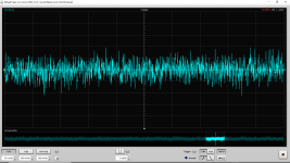
- [50uV/Div Voltage Waveform] All DAC Power Off
- [50uV/Div Voltage Waveform] DAC Output Powered
- [50uV/Div Voltage Waveform] All DAC Power On, Idle
- [50uV/Div Voltage Waveform] 1kHz Full Scale
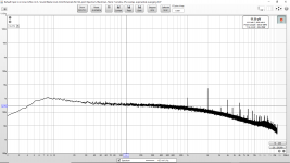
- [Spectrum] All DAC Power On, Idle
- [Spectrum] 1kHz Full Scale
Attachments
-
 Spectrum Input to AMS1117 Powered On 18650 Batteries to LM7805 DAC 1kHz Full Scale.png74.1 KB · Views: 137
 -
 Spectrum Input to AMS1117 Powered On 18650 Batteries to LM7805 DAC Idle.png76.2 KB · Views: 219
 -
 Input to AMS1117 Powered On 18650 Batteries to LM7805 DAC 1kHz Full Scale.png135.8 KB · Views: 216
 -
 Input to AMS1117 Powered On 18650 Batteries to LM7805 DAC Idle.png135.7 KB · Views: 214
 -
 Input to AMS1117 Powered Off Output Power On.png53.4 KB · Views: 217
 -
 Input to AMS1117 Powered Off Output Power Off.png58.3 KB · Views: 212
Now AVCC_R: The scale is 50uV per division for the voltage waveforms. Attached images in order:
- [50uV/Div Voltage Waveform] All DAC Power On, Idle
- [50uV/Div Voltage Waveform] 1kHz Full Scale
- [Spectrum] All DAC Power On, Idle
- [Spectrum] 1kHz Full Scale
Attachments
-
 Spectrum AVCC_R Powered On 18650 Batteries to LM7805 DAC 1kHz Full Scale.png78.2 KB · Views: 131
 -
 Spectrum AVCC_R Powered On 18650 Batteries to LM7805 DAC Idle.png80.8 KB · Views: 130
 -
 Voltage Waveform AVCC_R Powered On 18650 Batteries to LM7805 DAC 1kHz Full Scale.png96.7 KB · Views: 126
 -
 Voltage Waveform AVCC_R Powered On 18650 Batteries to LM7805 DAC Idle.png53.4 KB · Views: 133
kozard,
What does the same 3.3v input power look like with a scope (using proper probing and grounding technique). Reason I ask is because it isn't just audio frequency noise that can affect dac operation.
What does the same 3.3v input power look like with a scope (using proper probing and grounding technique). Reason I ask is because it isn't just audio frequency noise that can affect dac operation.
Now VCCA: The scale is 50uV per division for the voltage waveforms. Attached images in order:
- [50uV/Div Voltage Waveform] All DAC Power On, Idle
- [50uV/Div Voltage Waveform] 1kHz Full Scale
- [Spectrum] All DAC Power On, Idle
- [Spectrum] 1kHz Full Scale
Attachments
-
 Voltage Waveform VCCA Powered On 18650 Batteries to LM7805 DAC Idle.png92.5 KB · Views: 123
 -
 Voltage Waveform VCCA Powered On 18650 Batteries to LM7805 DAC 1kHz Full Scale.png88.7 KB · Views: 135
 -
 Spectrum VCCA Powered On 18650 Batteries to LM7805 DAC Idle.png80.4 KB · Views: 125
 -
 Spectrum VCCA Powered On 18650 Batteries to LM7805 DAC 1kHz Full Scale.png74.8 KB · Views: 130
1kHz Full Scale
Is that spur at 2kHz a harmonic of the 1kHz? like what if you change the 1kHz frequency, does the 2kHz spur follow it?
EDIT: I don't think anyone ever measured like you want to do. How will you correlate measured changes with how you judge the dac to sound? Otherwise, how do you know anything you do makes the dac sound better, worse, or has no effect?
Last edited:
kozard,
What does the same 3.3v input power look like with a scope (using proper probing and grounding technique). Reason I ask is because it isn't just audio frequency noise that can affect dac operation.
You mean the input to the 3.3V regulator? Or output of the 3.3V regulator?
Any chance you can make and post the same measurement? (And a quick picture/photo of where exactly you made the probe & ground connections?) I can try to copy within the limits of my equipment.
You may have misread my post. I also said that controlled listening tests (i.e. DBTs) are fine for testing. Have you conducted DBTs regarding the various tweaks proposed in this thread? What were the results?
Please stop insulting Markw4.
Ok. The HPRO power supply was a really bad idea. I thought a power supply for musical instrument effects processing would be pretty clean. I was wrong. The good news is that all these measurements just resulted in a massive improvement.
At least now your noise measurements are on par with what 7805+AMS1117 should deliver.
- Home
- Source & Line
- Digital Line Level
- ES9038Q2M Board