Braxy, all your Taobao links suck! Chrome translator completely craps out.1) I buy my TDA1387 from Taobao, here is just one seller : ?? TDA1387 ???????IC?? ??? TDA1387T ????-???
Been there, done that (passive I/V). For both tda1545 & 1387.The above is assuming you want the simplest form of I/V, passive I/V. .
No thx.
Hint: invest time (or $) in a good active stage.
Braxy, all your Taobao links suck! Chrome translator completely craps out.
lol, I have the same problem.
FWIW, I bought this one a little while ago
diyinhk i2s
Uses the latest xmos chip. Then I added a potato ff to reclock before the dac. Thats connected to my soekris dac.
This dac is connected to a pi3 then a allo kali reclocker.
Randy
Hint: invest time (or $) in a good active stage.
Preaching to the choir.
Look on my Hackaday project page, scroll down to 'Files' and its called lingDACfilter.pdf
Audiophile-sounding DAC for almost no money | Hackaday.io
Audiophile-sounding DAC for almost no money | Hackaday.io
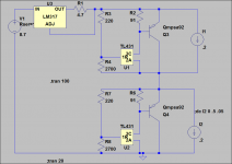
would be glad to have an active IV schematic 🙂..
Rudolf Broertjes’ SS I/V Gain Stage was first posted here on DIYA, back in 2003.
The design evolved a bit over at diyparadise.com
See:
Page 2 of THIS thread. I.e.,
TDA1387 continuous calibration dac
...and ...
Rudolf Broertjes' SS I/V Gain Stage - diyparadise
I use the above for my tda1387/1545a projects.
For tda1541a, I use Rudolf's other I/V .... also posted somewhere on DIYA.
I have a lot of hours on my 1387 DAC hat now, and I just cannot get enough of this thing! I have the Pi stack parked on top of my Carmody Sprite boombox in the kitchen. I love how it invites me into the music. When I stand directly in the seeet spot, I am continually amazed by the stage depth and the sweet, natural timbre.
I have a lot of hours on my 1387 DAC hat now, and I just cannot get enough of this thing! I have the Pi stack parked on top of my Carmody Sprite boombox in the kitchen. I love how it invites me into the music. When I stand directly in the seeet spot, I am continually amazed by the stage depth and the sweet, natural timbre.
😀
Hi math,I never had any mating problems on the GPIO pins. But indeed, I did have a bit of a gap between Kali and DAC. I think the Kali just has longer pins than the RPI.
In your video, when you get that perfect silence with the white three-prong: I can't remember, have you tried the iPower ground mod you mentioned before? You could whip up a ghetto one real quick with a paperclip and spare three-conductor power cord.
Also: I doubt the Kali is the problem, but take it out and see if the noise is still there. I assume it will be. But now, use something else to power the RPI + DAC. Surely you have a spare mini-USB cellphone charger. Then you can see if indeed that iFi power supply has issues. Also try powering using a USB cable from your computer to the RPI+DAC.
I'm trying to think of another common 5V power supply you might have in your house... do you have any spare PC power supplies? Those have 5V rails (google "ATX power supply pinout" for which pins to use).
In other news I moved the balanced version from the test rig to my main rig. I feel like this smooths things out a bit (could be my imagination). But I did quite a bit of listening yesterday and was really happy with the sound. Shorter XLR cables are on order. 🙂
Could you share please the balanced hat dac files, schematic, pcb layout etc
Very curious about this hat dac
Regards ,
Yo
Hi math,
Could you share please the balanced hat dac files, schematic, pcb layout etc
Very curious about this hat dac
Regards ,
Yo
See this post for the files
dac files
I was lucky enough to get one of Matt's boards. I am using it with a allo reclocker board, which does add to the cost, but I still think its a bargain for the sound quality of the DAC in that configuration.
Randy
Thanks Randy - but I believe Yosyos is asking about the balanced version, I don't think I ever posted those files. Let me do some digging, I've done a terrible job of keeping these things organized. I should be able to find them and post. (I also took a break from tda1387 to work on a tda8932 amp board).
Thanks randy but math is right i asked about the balanced versionSee this post for the files
dac files
I was lucky enough to get one of Matt's boards. I am using it with a allo reclocker board, which does add to the cost, but I still think its a bargain for the sound quality of the DAC in that configuration.
Randy
I'll wait patiently for the files
Thank's
Yosyos - also, I have a few spare unpopulated balanced boards. You can have a couple for free if you cover shipping. Definitely the quickest/easiest way to get boards if you're in the USA. But outside the USA, shipping can be expensive (probably at least $20 USD), so that's a harder call.
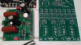
Front End v2.0 Files
Steering this thread back to the original topic for a second... 😉
A couple folks PM'ed me asking for the files for the version 2 front end. I want to revisit this design ("version 2.1" so to speak), as I think some things can be done better. But I don't know if I'm going to get around to this any time soon. So I'm posting the version 2 front end files as-is, for those who are brave, willing to debug my errors, and don't want to wait for v2.1. Please note: I have never had this design fabricated, so I can't vouch for its correctness. I repeat, this is an untested design!
Other than the images of the board, the attached files are as follows:
Note on KiCad files: these files are unlikely to be usable without some effort. I started with the current stable production release of KiCad (v4.0.7). Then I did multiple in-place upgrades using the nightly builds (i.e. version 5 "beta"). Because of that, I am almost certain these files will not work with KiCad 4.0.7. Furthermore, on another PC, I did a fresh install of KiCad nightly builds (as opposed to an in-place upgrade). This made me realize that KiCad has completely re-vamped the symbol and PCB footprint libraries. The net result is files that are in the new version 5 format, but reference the old version 4 libraries. KiCad can mostly auto-correct the symbol libraries in the schematic, but as far as I can tell, the PCB footprints have to be manually corrected. And I've found in some cases the new footprints are every-so-slightly different, enough that routing sometimes has to be fixed. The long-term plan is to get all my designs to be "purely" version 5 compatible, but that could be a while. 🙂
So again, I am posting these files only for the adventurous, as this design has never been fabricated and is completely untested. I just wanted to make these available for the people who PM'ed me asking about them. As I said above, I do want to revisit this design, have it built, and test it. But that could be a while (probably months), so here's a stop gap if you're interested.
Thanks!
Steering this thread back to the original topic for a second... 😉
A couple folks PM'ed me asking for the files for the version 2 front end. I want to revisit this design ("version 2.1" so to speak), as I think some things can be done better. But I don't know if I'm going to get around to this any time soon. So I'm posting the version 2 front end files as-is, for those who are brave, willing to debug my errors, and don't want to wait for v2.1. Please note: I have never had this design fabricated, so I can't vouch for its correctness. I repeat, this is an untested design!
Other than the images of the board, the attached files are as follows:
- Schematic in PDF format
- Gerber files generated by KiCad - I generated these the way I always generate Gerbers through KiCad, and it's always worked for Elecrow. But again, I haven't had this particular design fabbed. So I strongly recommend you sanity check these any way you can before paying to have them fabbed.
- KiCad files (see note below)
- BOM in CSV format. This was auto-generated by "KiCad_BOM_Wizard" and is very "barebones". Let me know if you need help with part selection.
Note on KiCad files: these files are unlikely to be usable without some effort. I started with the current stable production release of KiCad (v4.0.7). Then I did multiple in-place upgrades using the nightly builds (i.e. version 5 "beta"). Because of that, I am almost certain these files will not work with KiCad 4.0.7. Furthermore, on another PC, I did a fresh install of KiCad nightly builds (as opposed to an in-place upgrade). This made me realize that KiCad has completely re-vamped the symbol and PCB footprint libraries. The net result is files that are in the new version 5 format, but reference the old version 4 libraries. KiCad can mostly auto-correct the symbol libraries in the schematic, but as far as I can tell, the PCB footprints have to be manually corrected. And I've found in some cases the new footprints are every-so-slightly different, enough that routing sometimes has to be fixed. The long-term plan is to get all my designs to be "purely" version 5 compatible, but that could be a while. 🙂
So again, I am posting these files only for the adventurous, as this design has never been fabricated and is completely untested. I just wanted to make these available for the people who PM'ed me asking about them. As I said above, I do want to revisit this design, have it built, and test it. But that could be a while (probably months), so here's a stop gap if you're interested.
Thanks!
Attachments
-
tda1387x8_front_end_v2_kicad_20180501.zip815.8 KB · Views: 199
-
 tda1387x8_front_end_v2_3drender_angle2_20180501.jpg116.2 KB · Views: 531
 -
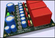 tda1387x8_front_end_v2_3drender_angle1_20180501.jpg125.9 KB · Views: 537
 -
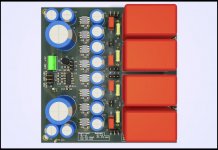 tda1387x8_front_end_v2_3drender_top_20180501.jpg108.5 KB · Views: 550
 -
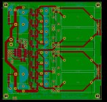 pcb_filled_20180501.jpg238.1 KB · Views: 562
 -
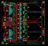 pcb_unfilled_20180501.jpg277.6 KB · Views: 554
 -
tda1387x8_front_end_v2_gerber_20180501.zip85.8 KB · Views: 177
-
tda1387x8_front_end_v2_schematic_20180501.pdf88.2 KB · Views: 505
-
tda1387x8_front_end_v2_BOM_20180501.csv.txt1.8 KB · Views: 188
Hello
I have a question about the tda1387 , is it compatible with a TDA1545 in PHILIPS CD723 ?


Thanks
Serge
I have a question about the tda1387 , is it compatible with a TDA1545 in PHILIPS CD723 ?
Thanks
Serge


The SAA7372 does support I2S amongst its many options for output but you'd have to get in and hack the firmware to adjust the setting of register 3. Not for the faint hearted 😛
- Home
- Source & Line
- Digital Line Level
- tda1387 dac pcb "front end"