Hi Marcel. I got a price for boards with the custom layer stack from PCBway - 350USD for five boards (plus shipping if I'm reading things correctly so I guess nearer to 400USD).
In the absence of anyone else being interested (I've had no response to my previous post asking for expressions of interest), should I choose to go with your board I will probably have to go with EuroCircuits.
I was hoping this newer, simpler board would be cheaper than that.
It is smaller, but still rather large: 195.58 mm wide and 314.325 mm long. The price at Eurocircuits is euro 256.92 including 21 % VAT for a single board, increasing the delivery time to 25 days does not change the price. Five boards cost euro 573.54 including VAT at Eurocircuits.
I think the only way to make this project affordable is to make it modular and simpler as per the suggestions I made previously, in fact I'm thinking it may be possible to go even further and I did some more work on it as part of learning KiCad last evening.
At the moment I'm just focussing on the core of the DAC. I've stripped out everything from the schematics apart from the left and right cores and the voltage reference section and have updated the PCB accordingly.
With this configuration, apart from the clock and data input sections, the DAC core is essentially traditional valve/through-hole technology so I took a backup and made the board two-layer - I plan to move all the remaining components to the top of the board and make the bottom a ground plane. With multiple power voltages to distribute across the board some of the track routing might get interesting. Although the board won't be small, it will be quite a bit smaller and changing to two layers will make it a lot more affordable, especially by eliminating the custom layer stack requirments and albeit being a bit less tidy because of the need for more connections to the board, for example, the off-board power supplies.
If I can get the DAC core sorted and affordable I will work on making a sub-board with all the data/clock handling that will sit underneath the DAC core board (noting Marcel's earlier comments about crosstalk between the sections). I'm thinking the ground plane under the DAC core boards will provide some screening between the two boards.
Power supplies will be seperate so there's planty of flexibilty around what to use - just need to pay attention to getting everything correctly referenced to ground.
I will welcome any thoughts/observations? Am I being naive and making too many compromises?
Ray
Last edited:
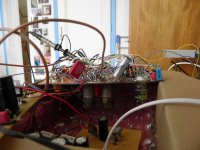
Attached are two pictures of my first prototype, which got its data from a makeshift analogue sigma-delta modulator built on a piece of perfboard. This was just to try it, as I could only go from analogue to digital and back to analogue with it. It worked, apart from some crystal oscillator issues, and music played though it sounded OK, but I did hear some soft background hiss and the hiss got worse by 10 dB or so when I touched the insulating sleeve of the coaxial cable that goes from the sigma-delta to the DAC. Clearly the noise floor was determined by the layout/crosstalk rather than the circuit. I didn't bother doing any noise measurements on this version.
Trying to reduce crosstalk as much as I could, I later went for the well-known four-layer board for the final circuit, with a ground and a -300 V plane as shields between digital and analogue/mixed signal. I made some mistakes, though, which initially led to a rather disappointing noise floor, just below -70 dB(A) if I remember well. After debugging, I got the -85.76 dB(A) and -91.29 dB(A) figures quoted in the article using the PWM8 algorithm. These are poor values compared to most solid-state DACs (as was to be expected with such a relatively simple circuit), but in practice they are good enough for me not to hear any hiss.
My guess is that your two-layer version will end up somewhere in between these two extremes, I can't predict where though. The fact that the clock and clockn lines are driven from a much lower impedance than in the original will definitely help.
Attachments

By the way, you will have to use at least 2.5 mm of clearance between ground plane and any traces/holes that are close to the negative supply because of the voltages and the fact that the ground plane will be on an outer layer (which can get dirty, unlike inner layers - of course there is solder mask, but that can easily get damaged).
To keep the board from bending during production, you will also have to put ground fill on the other side, again with enough clearance. If there are any traces on the bottom side, cutting gaps in the ground plane, it is advisable to put vias on both sides of them so return currents that want to flow through the ground plane but can't because of the gap can switch to the top ground fill and back to the bottom ground plane.
To keep the board from bending during production, you will also have to put ground fill on the other side, again with enough clearance. If there are any traces on the bottom side, cutting gaps in the ground plane, it is advisable to put vias on both sides of them so return currents that want to flow through the ground plane but can't because of the gap can switch to the top ground fill and back to the bottom ground plane.
Thanks for the further feedback and advice Marcel.
"OK" makes it seem like the sound quality was pretty mediocre, if that was the case why did you persist with a follow up and lots of debugging?
Regarding the two layer DAC core board, a ground plane on the bottom of the board will provide some noise improvement but I'm thinking that the layout of the clock board will also help, for example, if the components were to be on the bottom, relative to the DAC core board, with another ground plane on top, or maybe it could be four layer with additional screening (no special layer stack would be required either), or perhaps some sort of grounded 'boxes' over the different sections?
Ray
...and music played though it sounded OK...
"OK" makes it seem like the sound quality was pretty mediocre, if that was the case why did you persist with a follow up and lots of debugging?
Regarding the two layer DAC core board, a ground plane on the bottom of the board will provide some noise improvement but I'm thinking that the layout of the clock board will also help, for example, if the components were to be on the bottom, relative to the DAC core board, with another ground plane on top, or maybe it could be four layer with additional screening (no special layer stack would be required either), or perhaps some sort of grounded 'boxes' over the different sections?
Ray
Hi Ray,
I had no clue OK has that meaning to you, as I am a slightly autistic Dutchman, not a neurotypical native speaker of English. What I meant is that I heard no shortcomings other than a slight background noise at high volumes. I didn't spend too much time listening to it, though, as the main purpose was checking whether the valve circuits would work at all.
I think the main thing is how to place the components that you move from the bottom of the DAC board to the top and the lines that conduct the sigma-delta modulates to those components. Keep a few centimetres of distance from the clock, clockn and ref and all circuitry connected to those lines if you can.
Besides, try to ensure that return currents can flow back without major detours by doing what I wrote in post 125 and by placing C34 and C25 close to U27 (and the same for their right-channel colleagues). The biggest mistake I made on the four-layer board was not having C34 and C25 at all initially.
I know of FM radios with digital IF processing that work well on two-layer boards. Those are far more critical than this DAC, but with a really good board layout they can be made to work well.
I had no clue OK has that meaning to you...
Hi Marcel. Maybe I was a little inconsiderate not thinking through that English is not your first language. It's good that we only have these nuances of English to stumble over though; it would be impossible to conduct this exchange if we were using the Dutch language.
To me, saying something is OK is rather damning it with faint praise as it isn't a superlative like, for example, 'excellent' or 'marvellous'.
Anyway, I did some more work on the DAC core board last evening so I've learned a bit more about KiCad and moved more of the components to the top of the board. In so doing I've had to delete some tracks so have something of a rats nest to resolve but there's a good amount of empty board appearing so I'll be able to resize it soon - when I do that I'll generate some gerbers and get a cost estimate for the smaller, two-sided board before investing the time sorting out the detail.
Ray
I should have thought of this before but after my last post I used the JLCPCB instant quote tool; assuming I reduce the PCB size to 250mm x 190mm, five 2-layer boards, 2mm thick and with 1oz copper will cost around 70USD including delivery (an SMD stencil will add perhaps another 15USD).
For the clock/data processing board, assuming a size of 190mm x 100mm, five 4-layer boards, 1.6mm thick and with 1oz copper will be about another 50USD - obviously just a very rough estimate at this time.
Those costs look a lot better.
Ray
For the clock/data processing board, assuming a size of 190mm x 100mm, five 4-layer boards, 1.6mm thick and with 1oz copper will be about another 50USD - obviously just a very rough estimate at this time.
Those costs look a lot better.
Ray
Last edited:
I joined this conversation late, post the initial board group buy attempt, paid for Marcels descriptive document which was read with fascination and I am following this thread with interest.
I wish I could contribute at this stage however this is way above my pay grade.
I’m an engineer by trade so when you need an enclosure at cost or if I can find something in my scrap bin then postage only.
I just wanted to raise my hand on this project and contribute what I can. I really want to see it live.
Snax
I just wanted to raise my hand on this project and contribute what I can. I really want to see it live.
Hi snax and thanks for your kind offers. This is all a steep learning curve for me but, with Marcel's guidance, I'm hoping I'll get to a point of having something that has a good chance of working well. Fingers-crossed!
Does your post imply an interest in building one? My interest is in the DSD-only version but I don't think the changes I'm making will preclude a PCM version.
As a backstop (or maybe even as a preference), with some more interest it becomes viable to purchase a batch of five PCBs using Marcel's board design.
Whereabouts in the UK are you.
Ray
Hi Ray,
I have already started ordering parts to Marcels origial design.
I was steeling myself to the soldering of surface mount components of which i have had some success and some expensive failures due to being an ocd perfectionist.
I was about ready to order a singel board but saw your suggestion of making the boards modular. I will wait to see what transpires...
Based in West London but dont spend enough time at home to make it count.
Dan
Hi Dan.
Let's see how it goes, though it may take a while for me to learn enough to get a basic board layout. Is your interest DSD or PCM data input? As I said I'm only working on DSD input so some additional work would be needed for PCM.
Assuming we have a shared goal, If I can pull it off I may be able to help out with the smd work as my PCB should fit into my mates reflow oven; having to hand solder Marcel's board, which is too large, isn't something I would look forward to, especially with smd parts on both sides of the board - feels like a recipe for tears
@ Ray - I am still reading as to which format and to be honest I would not want to steer the ship / design. In this environment I am happy to sit and listen / learn.
@ Marcel, I really like what you have started here.
I would hazard a guess that the clock should be solid state and the frequency is what you are able to adjust via the FPGA?
Have you not suggested a 27MHz crystal in your Schema?
I have only dabbled into the realms of the possible with valves as I am a recent convert of the last 15 years and only ever for amplification, so what would you use as a clock?
When i saw this thread, it just reminded me of a moment in time where I first heard a valve amp having been a solid state advocate, and it sparked my imagination. My enthusiasm is currently driving me on, I just need to hear something and I will be hooked.
Hi Dan, thanks for the compliment!
When you compare my original design and the raw-DSD circuit Ray is working on, these are the main differences:
Original:
-Mainly designed for PCM; generates its own sigma-delta modulates from a PCM input signal using the FPGA module and the SRC4392
-Supports DSD64 and DSD128 by first converting them to PCM
-Valve clock generator (just because I wanted to make all analogue and mixed-signal functions with valves)
-Quite expensive
-Tried and tested
Raw DSD version:
-Gets its sigma-delta modulates from an external source (DSD is basically a Sony/Philips trade name for a sigma-delta modulate), so it doesn't need any FPGA or SRC4392
-Can support DSD256 and DSD512, if my calculations are correct
-Gets its clock from an external solid-state clock generator and buffers it with some more solid-state circuitry
-Much more affordable, especially after Ray's changes
-Not tried and tested yet
Now suppose you would want a DAC optimized for PCM and that you had no objections against solid-state clock generation. You could then make something in between by putting a solid-state clock generator and the FPGA section of the valve DAC on a separate module and connecting it to the circuitry Ray is working on. The DAC and voltage reference board could then be exactly the same as what Ray will be using for raw DSD. The whole DAC would be more expensive than the raw DSD version, mainly because of the FPGA module, but still less expensive than the original.
Hi Dan. Marcel can explain the differences between the PCM and DSD versions with authority but in simple terms the starting point is that the core of Marcel's desgn is a single-bit DAC. DSD is a single bit format so the core's can be driven directly by the DSD clock. PCM is multibit so Marcel uses additional circuitry to resample to one-bit data at 27MHz as per his original design.
I'm a fan of DSD and I use Signalyst HQ Player to resample/upsample my PCM (FLAC) files to DSD on the fly (in simple terms doing essentially the same work as Marcel's FPGA based front end). I've almost completed a project to build a Signalyst DSC 'DAC' using ppy's boards and the DSD Valve DAC will be an excellent follow on project, even further from the beaten track. BTW, I plan to use a Beaglebone based isolator/reclocker, running Signalyst software, on the front end of the Valve DAC.
My amps are also off the beaten track; I love what OTL amps do and I currently use scratch build variations of the Transcendent 300B SE-OTL - four 300Bs per channel to get about 1.5W of output (into 8ohms, though I use 15ohm speakers making the life of the amps easier). I'm working on a new SE-OTL amp project that will use one 13E1 per channel to give around 2watts into my 15ohm speakers and I have plans for an even more esoteric OTL amp beyond that.
Back on topic, today I have been looking into how KiCad enables PCB modules that can be reused so, to make use of what I've learned over the last few days, I started afresh on my PCBs this evening - I will now produce PCBs for each module (DAC core, V Ref, etc) that I can then integrate into larger boards. To start I'm working on the DAC core for just one channel that, once finished, I can replicate for the other channel on a stereo board.
Ray
Last edited:
Pardon if this has been asked and answered earlier: Have you measured these DACs?
Tom
For the original DAC, the answer is yes, for the DSD only version (which doesn't exist yet), it is no.
Pardon if this has been asked and answered earlier: Have you measured these DACs?
See Marcel's published design documentation.
- Home
- Source & Line
- Digital Line Level
- Valve DAC from Linear Audio volume 13