Asked the information to Sowter. Now time to play with the scope looking for the best squarewave @ 1kHz, thanks abraxalito.
Attached pics of scope, one direct to SG and the other to the 100K dummy load, finally resistor 3k61 so I will use standard resistor 3K6.
It's necessary the output coupling capacitor after the 1:1 transformer?
It's magic, no cliks or pops changing between PCM & DSD. I still need the output capacitor to avoid DC: I have AVC at the input of preamp or headphone amp and don't likes DC, I listen scratches when I turn the volume.
Merlin, take the 10KHz or 15KHz square w measurements to determine RC notch at the secondary of the transformer. 1KHz is not good choice since transformer have ringing on higher F above 10KHz...
Probably You will have to use analog generator for this, because most digital sources incapable to produce clear square at theese F. They starting to bend the square from 2kHz. Also try to use similar or same generator internal resistance like you will use in digital real circuit.
Point is as much smaller C and as bigger R to find for cutting out ringing. Strat with higher value of R and small value of C. After that You can use termination resistor, but bearing in mind next resistor in next device peamp. And if the RC notc are good You can use higher value of terminating R avoiding compression. Take a look about this issue in Jensen papers.
cheers
Last edited:
Have I to kept also the secondary RC network?
I would, if I were you.
You can make a resistive divider to give ~50ohms output impedance. Just a 560 ohm in series with 51ohm to ground.
Last edited:
I would, if I were you.
You can make a resistive divider to give ~50ohms output impedance. Just a 560 ohm in series with 51ohm to ground.
The divider is for the SG right?
@abraxalito
Mine friend Jordi from Tarragona sent me today a couple of tx 15K : 300Ω that I want to try in place of 1:1 tx
I have several doubts about reflected primary impedance can affect your 50Ω characteristic impedance filter to match de Amanero 50Ω output impedance.
Mine maths helped with other forum members are:
-Impedance ratio 50:1 (15000:300)
-Impedance ratio square root 50 = 7 aprox. = 7:1 turns ratio
-15K secondary tx in parallel with 100K load (26 preamp or 5687 headphone amp) = 13K043 secondary load
-13K043 secondary load / 50 impedance ratio = 260.86R reflected primary impedance instead 300R
¿Loading opt tx x2 or x3 times so 50Ω x2 or x3 times = 100 or 150 Ohms and here is x5.72 times this can affect the Amanero's output impedance of 50Ω & your filter?
I'm only a beginner with impedance specs of trafos but those impedance figures represent the load impedances not the characteristic impedance(s) of the windings themselves.
The impedance factor of 50:1 means 100k from your preamp becomes 2k at the output of the filter, this is about 2.5% reduction of 50ohm not really a problem, you could increase the 50ohm load resistor to 51ohm but I doubt its worth the effort.
Thanks abraxalito.
To use the 15KΩ-300Ω OPT have I to kept the same 3300uF to avoid the leakage inductance of OPT like the 1:1 OPT or have I to change something?
I would, if I were you.
You can make a resistive divider to give ~50ohms output impedance. Just a 560 ohm in series with 51ohm to ground.
I guess 1/4w resistors is enough?
@abraxalito
I make the network 560R series with 51R to ground at the SG output to do the measurements.
Ouptut SG 1Vpp 10kOhms, output LCLC LPF 0.2Vpp, filter loss 80%?
@Zoran
Using the same network to adapt output impedance of SG to 50 ohms I measured the OPT ringing
Ouptut SG 1Vpp 10kOhms, output OPT (300ohms/15kOhms) needs an RC filter of 14Kohms 100nF
@Both
Now time to measure the LCLC low pass filter together the OPT to measure ringing to calculate the proper RC filter.
Thanks guys.
Cheers
Felipe
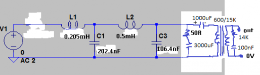
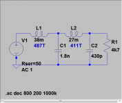
Attached last schematic I'm using.
How's it working for you Felipe? Good sound, any noise, pops, etc?
Here's a variant of the noDAC filter designed for use with an active buffer (Zout is 4.7k). It has a loss of only 0.2dB.
Thank you very much, the filter have two specs that I like very much: one is the low loss & the other is the output impedance that I guess will match very well with the 100K input impedance of the next source, if I calculate well with OPT 600/15K will reflect 4K, it's OK?
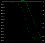
What kind of filter is: Bessel, Butterworth, etc?
Whats the corner frequency: 50KHz?
Last edited:
How's it working for you Felipe? Good sound, any noise, pops, etc?
No pops, cliks only first time before playing the first song, only a little background ultra low noise a lot less than playing vinyl records, about good sound I sold the couple DSC with NXP that I bought time ago.
... the output impedance that I guess will match very well with the 100K input impedance of the next source
The output impedance of this filter is well suited to a local buffer's input. Its not suited to feeding to another piece of equipment without a buffer between.
if I calculate well with OPT 600/15K will reflect 4K, it's OK?
I'm unclear how you're thinking of connecting the transformer. This filter isn't suited to driving a transformer directly.
The filter's a Butterworth, 4th order with an fc about 30kHz.
Last edited:
- Status
- This old topic is closed. If you want to reopen this topic, contact a moderator using the "Report Post" button.
- Home
- Source & Line
- Digital Line Level
- low pass filter for DSD