I'm pretty sure we're all I2S.
I've sent questions to Allo about their Kali board connections with the Najda info I have..
Hoping they'll take a look at Nadja side too and point me in the right direction 😉
In the meantime I will try the various DAC options in RPi (Volumio). Could be something other than I2S generic might work?.. but I doubt it somehow.
Update!
It's a good job I'm a persistent bugger!
After getting a weird sped up effect (like Pinky and Perky..) when I accidentally tried the Pro I2S dac setting in Volumio when messing with my ordinary Hifiberry, I thought there might be something in Volumio going on stopping the RPi I2S into Najda working as it should.
After trying several settings and getting stuck on the Allo Piano 2.1 I2S DAC setting (rendering RPi unreachable by IP address and it even seemingly toasting one SD card), the next I2S DAC selectable in Volumio was Apple Pie DAC!
You can see I'm still on A out of all the letters.. there must be some 40 or 50 selectable!
It only works.. & plays
Can't you hear me knocking by The good old Rolling Stones perfectly!!!!!!! Yes I know more than one ! is bad taste.
All other problem tracks are fine too.
Balance is seemly fine too.
Now to customise some more save the config file and then have me some quality time evaluating RPi..
Hopefully Allo will get back to me with other even better suggestions, but for now it sounds ok.
I might even try it without Kali at some point.. but not for a while.
The more I listen the more in liking it.
Easy to A/B compare at the touch of a button with ChromeCast Audio too!
I2S when it works it's the future haha..
Last edited:

Hi Steve,
thanks for sharing your findings! I line in with others observing the balance is not quite right using RPi - I2S - Najda!
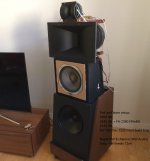
In your post from 30th December 2018 you write, you use separate power supplies for RPi and Kali - would you tell us, which psu types you use?
Am I understanding right that you use the "Apple Pie DAC" setting in Volumio? (I´m trying KODI instead at the moment, so no quick try possible...)
Is this setting healthy without Kali, too?
Can you please give us an idea if RPi - Kali - I2S - Najda is better sounding than RPi - I2S - Najda?
On our way to a better sounding 2019!
thanks for sharing your findings! I line in with others observing the balance is not quite right using RPi - I2S - Najda!
In your post from 30th December 2018 you write, you use separate power supplies for RPi and Kali - would you tell us, which psu types you use?
Am I understanding right that you use the "Apple Pie DAC" setting in Volumio? (I´m trying KODI instead at the moment, so no quick try possible...)
Is this setting healthy without Kali, too?
Can you please give us an idea if RPi - Kali - I2S - Najda is better sounding than RPi - I2S - Najda?
On our way to a better sounding 2019!
Hi Steve,
thanks for sharing your findings! I line in with others observing the balance is not quite right using RPi - I2S - Najda!
In your post from 30th December 2018 you write, you use separate power supplies for RPi and Kali - would you tell us, which psu types you use?
Am I understanding right that you use the "Apple Pie DAC" setting in Volumio? (I´m trying KODI instead at the moment, so no quick try possible...)
Is this setting healthy without Kali, too?
Can you please give us an idea if RPi - Kali - I2S - Najda is better sounding than RPi - I2S - Najda?
On our way to a better sounding 2019!
I'm using a dual output 5v linear power supply. One to the RPi and one to the Kali board. You remove a little jumper on Kali for this.
So far I've not tried the Apple Pi DAC setting in Volumio on RPi only.
It's a bit of a fiddle as I have to unplug lots and pull Najda out to get access, but I will do so soon.
It could be that it will work fine without Kali, but you read lots about the poor clocks of RPi.
There are lots of parameter changes possible to under volt and the like the RPi - some say they improve the sound. That's in the config file in the boot sector.. lots to try.
I've got WiFi, usb and Bluetooth all off. Not sure how much difference they make.
Could have been from early RPi days when things were marginal on power..
For the record:
RPi + Allo Kali reclocker users!
Good news!
Allo support got back to me.
They recommended setting the DAC model to R-PI DAC in Volumio. I just never got that far down the exhaustive list 🙂
This I did, and it did not crash the RPi or brick the SD card 🙂 Good start!
Also they said: "With Kali 24bit format does not play back properely. So enable Audio resampling on to 32bit."
I did this too and just had a little listen.
Sounds good!
Instrument placement and timing is as it should be on all my test tracks.
The very slight overall balance offset, still there on Apple Pi DACs setting, is now gone.
The Audio resampling setting does not affect Spotify etc.
It did change things on NAS file playback.
The lights on Kali change accordingly. I set the target sample rate to 96, as that is what Najda works at.
I have yet to try other settings. Most of the time I'm using Spotify anyway..
I re-asked Allo support if there is any other way of connecting Kali, using the MCLK etc, but I suspect I have it as it should be.
Hi to all of you,
I recently took some time to read everything from the very beginning. I tagged the following replies as highlights. There is a lot of tech talk, as a consumer however I am more interested in proper setting up the DSP. Maybe this is a little help for some others aswell.
Will be posting some more stuff soon, as I am building a new setup for my speakers.
Kind regards, Alex
I'm sorry, I'm unable to answer your question. Maybe Xav will when he has some spare time.
We're getting ready to release the software, so I'm posting a couple of screenshots of the IIR filtering mode (which is coming on top of the FIR Engine mode described earlier). If there's enough interest, we'll add gradually more meat into the software 😉 (How about a subtractive with Lipshitz-Vanderkoy delays? 🙂 )
Well for now it's a classic IIR. The input section:
View attachment 334719
So this is where it's all starting. The user supplies a stereo pair of inputs, and Najda transforms this pair into 4 separate signals (L, R, SUM, DIFF) with their own processing path.
In the above screenshot, only the Left channel processing path has something relevant in it (i.e. the other channels are unprocessed).
Processing begins with a 2500-sample delay (max 8191) followed by a -4 dB gain, and a set of 3 second order sections.
The second order filters that you have here are the ones that all of you have used: peaking/low shelf/high shelf. The peaking filter has of course adjustable Q factor and the shelves have adjustable slope.
I'm often asked: How many filters per channel do I get?
Well, Najda doesn't use a fixed processing path. You can see on the screenshot above the ADD SECTION button. Click this button and the application will add a filter to the selected channel. Click this button as many times as you like, there's no limit (well we've set a limit of ten for the sake of wisdom, but we could extend this to virtually any number).
Now an important point: you might remember that the monitor tab shows the DSP load. It's the user responsibility to make sure that the processing he's devising doesn't overload the DSP. In other words, while the user is adding filters, he should check the DSP load meters and make sure they stay below 100%.
This flexibility feature allows distributing the processing power where your system needs it instead of allocating a fixed number of filters to some channels you might not even use.
The next tab is the output processing.
View attachment 334720
On the far left, you're routing the signal. This means that you select one of the 4 processed channels we talked about earlier (Left, Right, Sum or Diff).
Routing is followed by a Pregain, then a group of 3 IIR blocks.
First block is the LowPass filter.
Second block is the HighPass filter.
Supported filters are
- Butterworth 6/12/18/24/36/48 dB/oct.
- Bessel 12/18/24/36/48 dB/oct.
- Linkwitz Riley 12/24/36/48 dB/oct.
Butterworth cut-off frequency is where the response is -3dB, as usual.
For Linkwitz-Riley, we also use the classic cut-off at -6dB.
Bessel filters are phase match - so there's no fixed dB number at cut-off. Instead, a low-pass and a high-pass with same orders and cut-off frequencies will have phases that are a multiple of 90 degrees apart at design frequency.
The cross-over design follows the same principle as the filter section I described earlier: a by-pass doesn't use processing power, and the higher the filter order, the more processing power it burns (so always check the DSP load meters!).
The crossover block is followed by the EQ block (peaking/shelves) which is identical to the one on the input processing tab.
Then you get the PostGain, the channel polarity invert and the output delay (4095 samples max).
As a quick and dirty example, here's what you can read on channel 6:
- Routing is the Diff signal
- Pregain -4dB
- Low pass F=1000 Hz Bessel 36dB/oct
- High pass F=100 Hz Linkwitz-Riley 48dB/oct
- Only 1 EQ section(it's a good driver 😉 ) which is a peaking filter with F=235Hz, 6dB gain, and Q factor 3.4.
- 3dB PostGain
- Polarity inverted (don't ask why 😛)
- 2345 samples output delay, which is 24.427 ms at 48 kHz sampling frequency.
Of course, the whole processing can be viewed on the graph tabs.
I have started to play with it...
On first picture where you can see measurement of a quick three ways Linkwitz Riley 4th at 150 and 2kHz. The additional high pass curve is the one with the the CS3318 set at 6.0 Vrms. Others are outputed with the nominal output set at 1 Vrms.
Second picture is to show the board configuration where you can set the DAC interpolation filter along with the nominal output.
Be aware of a small bug with the current version of software/firmware, the Bass / Trebble optional controls introduce a phase aberration even without any correction selected. Well, it took me a couple of hours, scratching my head with some measured phase deviation before tracking that one !
Jean Claude
A quick illustration of possible use:
on first picture, I have loaded the frequency response of a small mid woofer (Scanspeak 18W4531-G0 obtained by a combination of a near field measurement up to 250 Hz and a free field above on axis. No smoothing at all. You can see how well ScanSpeak was able to control the break up modes ! I love and use this driver by the way!
Chanel 8 is just here to illustrate the target (LR24 150Hz-2kHz).
The next picture is the same response corrected by only a Highself. not bad already !
xx_4a & 4b show you the same driver with the LR24 filters enabled and a couple of EQ added. Please note the vertical resolution (1 dB/step).
The result is quite good but we can see a deviation from theoretical below 100 Hz (only one half of an octave below the cut off freq).
xx_5a & 5b are just to show you that, sometimes, it's better to use different type and order for the filter to meet the target. We are now close to the target down to 60 Hz with the use of a Bessel third instead of the LR24 and all that with only 5 EQ beside the filter by themselves.
So what, at 300€ it looks to me a real bargain, thanks Nicolas. Of course there is a lot of room for improvement but with a firmware labeled at rev 0.3 and a software at rev 0.01 ? congratulation, you have already a winner
I'm just coming back quickly (!) to the FIR filters that Paal has designed. Paal sent me his coefs - I hope he won't mind if I post a few screenshots here.
So I've loaded his coefficients on Ch1 and Ch2:
View attachment 336669
One filter is 512 samples long, the other one is only 256 samples.
The design procedure for FIR filters often yields to impulse responses that extend to infinity in the past ... and in the future, with (luckily) most of the energy being at the time 0 (the impulse response appears here in red). Time 0 is the time of now.
No computer, regardless of how powerful, can compute the output of a infinitely long filter. And no computer can guess what the samples of the future are going to be.
That's right, the theoretic model requires to know what the sound was before you were born. 😕
It also requires to know in advance what the sound is going to be long after you have died. 🙄
That's why we need to approximate this infinitely long filter by windowing its impulse response - i.e. keeping only a certain number of coefs and ignore the remaining ones.
So first thing we do, we keep N points of the impulse response symmetrically about time 0. This way we have a filter that expands only approximately N/2 coefs in the past and N/2 coefs in the future.
There's still this problem that the filter needs to know samples of the future. To go around this, we 'shift' the impulse response in the past so that the future becomes the present
The amount of shift is usually half the length of the impulse response, so for a 512-coef filter, the amount of shift is 256 samples. In clear, by shifting the filter so that we can implement it, we effectively introduce a delay of half the length of the filter.
This is why Paal introduced a delay of 128 samples on the tweeter channel. Indeed, the medium filter, by design, induces a delay of 256 samples meanwhile the tweeter filter a delay of only 128 samples. Thus Paal has time-aligned the outputs of both channels.
So here's what the frequency response of both filters is looking like:
View attachment 336673
As Paal explained, they combine a FIR approximation of a 4th order LR to some EQing.
I asked Paal to show how the channels sum together. Here's what he showed:
View attachment 336676
I frowned quite a bit when I saw this. There's obviously something wrong with this crossover. Or something wrong with the graph.
The fact is, the Summing feature in the graph utility doesn't take the delay into account. So this plot shows what the sum would be if there had been no additional delay on the tweeter channel. (Rest reassured I will fix that asap).
So I cheated. I opened Paal's tweeter coef file and I inserted 128 'zeros' at the beginning of the file. These zeros act as a delay: indeed, during the first 128 samples, the modified filter ignores the incoming samples (it multiples them by the null coefs).
Finally, I reloaded the file and suppressed Paal's original delay. I had now the medium's 512-coef filter with a new tweeter 384-coef filter equivalent to Paal's original design.
View attachment 336679
Again, I checked how the channels were summing, and here's how it looks like:
View attachment 336680
Isn't it looking much better? 🙂 If there was no EQing, the channels would sum flat.
Conclusion: I think this crossover has a good potential. I'm looking forward to read Paal's comments on his listening session !!
I wouldn't worry too much about sample rate conversion.
I had a look a the application you have used so far, and suggest you just try rePhase (as recommended by a few forum members):
rePhase | Free Audio & Video software downloads at SourceForge.net
Not sure whether you need this, but here's a simple example: I want to design a 3-way FIR crossover that mimics LR 48 dB/oct. (it's just a simple example in order to illustrate, don't ask me why LR 48 dB/oct 🙂 ). I want one crossover at 400 Hz and another at 4 kHz.
So let's open rePhase and build this crossover together.
View attachment 340970
I've circled the important fields.
On the right, from top to bottom:
- The number of taps. More taps will allow you achieving a better approximation, at the expense of increased DSP load.
- The rate: select here 48 kHz (select the same in Najda).
- Format: 32-bit float txt. With this option selected, generated files are compatible with Najda.
- Filename: make sure to save your file under a proper name 🙂
On the left, select the 'Linear Filters' tab.
We generate first the low-pass coefficients. I've selected here 511 coefs, and rePhase signals a max deviation of about 2dB with regard to the LR model. Yeah why not. Let's keep it.
Now we generate the bandpass:
View attachment 340971
I've tried another number of taps (911). This time max deviation is only 0.22 dB. Fair enough.
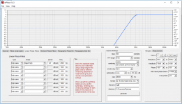
Finally we generate the high-pass:
View attachment 340972
In the high frequencies, I know I need less taps. I've tried 121 and it seems fine, with a max deviation of 0.00...
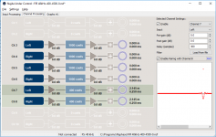
Now I can load the files in Najda Under Control:
View attachment 340976
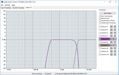
I can check the plots in Najda:
View attachment 340977
Well it's crossing at 400 Hz and at 4 kHz, so we're happy aren't we? 🙂
What would be the sum?
View attachment 340978
Oh no! what is that??? 😡
Alright, that's a time-alignment issue because filters have different lengths (= different numbers of taps).
Looking again at the 3 rePhase screenshots, we can see that:
- The low-pass has an offset of 256 samples
- The band-pass has an offset of 456 samples
- The high-pass has an offset of 61 samples.
We need to compensate for that.
The band-pass has the largest offset = largest delay. We leave it as is.
Then the low-pass requires a delay of 456-256 = 200 samples.
And the high-pass requires a delay of 456-61 = 395 samples.
View attachment 340979
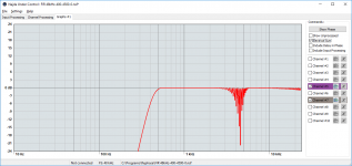
Now we can check the sum again. Make sure to check "Include Delay in Phase".
View attachment 340980
So it's not perfectly flat because we didn't have perfect LR filters at the start.
Anyway, looking at the scale, the residual dip is quite small.
(Note:
In Najda's graph view:
- Click and drag to move the 0dB line up and down.
- Click+mouse wheel to zoom in/out
- Double click to reset the graph to original view)
Alright, we've here approximated a LR network. We could actually approximate anything (anything reasonable). You could load in rePhase your measurements, build a crossover and add EQing...
Hope this helps.
Nick
Thanks Ake. I had a look at your setup file and you have nearly 24 dB gain at 50 Hz, and it's still growing towards the lower frequencies with 33 dB at 20 Hz.
If you need so much bass boost, then you must provide a similarly large headroom. Let me try to explain this briefly (and sorry if I say things you already know):
- Digital content (via SPDIF for example) reaches the DSP at a normalized level. This means that the content will hit 0dBFS (FS stands for Full-Scale) from time to time (if you're listening to classical music) or all the time (if you're listening to modern pop or DJ stuff).
- If you add 1 dB of gain in the DSP, then this is enough in theory to clip the signal: everything beyond 0 dBFS is clipping.
- Your setup shows more than 20 dB of boost in the region F < 60 Hz: any content with bass hitting full-scale will require at least 20 dB of headroom.
I'd say you should set more than 15 dB of attenuation on the input signal if you want to keep the setup the way it is now.
There are probably ways to improve your setup.
1. The HF band doesn't need so much headroom. So you should be able to optimize the headroom for each of the frequency bands. Start by moving the input gain to the channel processing pre-gains as illustrated below (the input gain is now 0 dB).
View attachment 381079
2. Now you can increase the pre-gains in channels 1 & 2 (driving HF) until it starts clipping. A wild guess based on your filters is that you would need only -8dB of gain. This is pictured below. Note that I've moved the corresponding gain difference to the post-gain in order to keep your balance HF/LF as before.
View attachment 381084
3. You could now move the above -9.5 dB post-gain to the analogue gain section.
4. There's probably something wrong with the sub management: you set a 5 dB post-gain in the digital domain, with no prior headroom provision. This is going to clip. Easy solution: move that post-gain to the analogue gain section.
Nice! Had seen it already on ze french forum 😉 Pity for the front plate but it's not a drama either and can be fixed with a bit of TLC.
Very nice Urban! Looking forward to your impressions!
If I understand correctly, you want to know if Najda lets you design phase coherent/integrated crossovers.
Well, yes. But this all depends on the crossovers you design. In this post I will assume you will be working in IIR (Which is the "Standard crossover/filters" mode). There is no individual phase correction or linear phase filtering in IIR mode, so you have to be careful with phase alignment. This is not specific to Najda, this goes for ALL kinds of analogue and IIR crossover design.
For drivers to be phase aligned at crossover, you can go down many paths. Different crossover steepnesses require different kinds of care to be taken.
IIR filtering works with the exact same phase/transfer functions as analogue/passive filters. That means that each 6dB/oct of IIR filtering produces a 45º phase shift at crossover point, exactly like the analogue equivalent. Additional steepnesses (12/18/24/48) are essentially many 6dB filters cascaded on top of eachother, so that a 12dB/Oct filter creates 90º phase shift, just as a 24dB/Oct makes for 180º.
A low pass filter will create a phase shift inverse to what an equivalent high pass filter would do. That means that if you cross two drivers at 12dB/Oct, say a midrange driver and a tweeter, you have a midrange lowpass filter that shifts 90º to the left, and a tweeter highpass that shifts 90º to the right. Comparing these, your drivers are now perfectly OUT of phase at crossover point (180º apart from eachother), meaning they will move inversely to eachother. The easiest way to work around this is by inverting the polarity of one of the channels (Say the highs) by using the Invert Phase function in NUC or by simply inverting the +/- on your drivers as is done with most passive crossovers.
Taking this logic further, for example with a textbook 24db/Oct filter, you will see that each filter (both the midrange lowpass and the tweeter highpass) now have a 180º phase shift each, producing a total of 360º, meaning that their phase shifts line up perfectly. Thus you do not need to invert your driver polarity for a regular 24dB crossover.
Now, it's important to note that text-book crossovers like these are not always (rarely, actually) the answer in the real world, and that there are things that are more important than perfect phase integration. Often you will see people crossing drivers using for example 12dB for midrange lowpass, and 24dB for tweeter highpass. This works well, because even though the drivers are technically out of phase by 90º that's not enough for the drivers to be cancelling each other out, and often has other benefits to the overall sonic performance of the crossover. There are many common variations.
Two other things you need to remember are:
- EQ. IIR EQing creates phase shifts in the same fashion as the crossovers. If you need to do EQing close to the crossover point, you might want to do that in the Input section of the Najda instead of the channel outputs, so that both sides of the crossover gets the exact same phase skews applied.
- Time alignment. When it comes to phase integration, this is perhaps the most important point of them all. No matter how perfect your phase integration is on the DSP side, it won't matter unless your drivers are not aligned perfectly distance wise. For example, a common problem is that when the tweeter and midrange are mounted on the same baffle, the center of the midrange speakers is usually further away from your ear than the center of the tweeter. This is why you often see tweeters recessed or speaker cabinets tilted backwards in high end commercial speakers. With a digital crossover such as the Najda you can compensate for this by simply delaying the tweter's signal by the time equivalent of 1-2cm, relieving you of having to make clumsy speaker design decisions.
so, TLDR: Yes, you can make perfectly phase integrated crossovers with the Najda, but as with everything else it requires careful design and consideration.
(DISCLAIMER: Ramblings above are based on my understanding of the subject and are not guaranteed to be correct. Feel free to correct me.)
Hi folks,
there is a new Najda under Control on the WAF-home page ! Version 1.1.5🙂
Hope it helps,
Rainair
there is a new Najda under Control on the WAF-home page ! Version 1.1.5🙂
Hope it helps,
Rainair
Najda under Control Version 1.1.5🙂
Rainair
Did instal but can not find any visible new. Provable some kind of bug or driver fix.
But still, a surprise as I more or less have thought that what we have is what we are going to get.
I think Najda is still very competitive as it has all you need to run it in a family living room. It also is a tool to set up multiway active speakers and try on them different settings and filters for eq and also room correction. And the boxed version is very nice and gives a professional feeling. And the price is very competitive.
The lack of taps is something we will run into on more or less any platform.
Many are running their FIR filters on PC with Jriver. So my wish would be to be able to port 8 channels USB into Najda. miniSDP USBStreamer wold give the connection to the PC.
Attachments
Good day,
NUC 1.1.5 was made available in August last year. 🙂
It's a maintenance release fixing bugs and also contains the most current version of USB drivers. The graph utility was updated - hopefully that's going to fix the issues that some of you have noticed with measured data.
Cheers,
Nick
NUC 1.1.5 was made available in August last year. 🙂
It's a maintenance release fixing bugs and also contains the most current version of USB drivers. The graph utility was updated - hopefully that's going to fix the issues that some of you have noticed with measured data.
Cheers,
Nick
Good day,
NUC 1.1.5 was made available in August last year. 🙂
It's a maintenance release fixing bugs and also contains the most current version of USB drivers. The graph utility was updated - hopefully that's going to fix the issues that some of you have noticed with measured data.
Cheers,
Nick
Hi Nick, glad to see you back there. Do you plan to produce new batches of Najda extensions on WAF site, or is it obsolete now ?
Any plans with Diy ?
BR
Jean-Louis
Hi JL,
I'm on a motorbike trip since last August, now in Ecuador and crossing into Peru next week.
I'm sorry to say but production is halted.
I have looked for a partner to take on manufacturing and distribution, unfortunately without success. I have no stock left.
Cheers,
Nick
I'm on a motorbike trip since last August, now in Ecuador and crossing into Peru next week.
I'm sorry to say but production is halted.
I have looked for a partner to take on manufacturing and distribution, unfortunately without success. I have no stock left.
Cheers,
Nick
Hi JL,
I'm on a motorbike trip since last August, now in Ecuador and crossing into Peru next week.
I'm sorry to say but production is halted.
I have looked for a partner to take on manufacturing and distribution, unfortunately without success. I have no stock left.
Cheers,
Nick
Hi Nick
Have a nice trip and take care. Hope to see you back here 🙂
Hi all,
I found a difference: The electrical sum: Include Delay is not working.
LG, Rainer
Have you pushed the "show phase" button?
br
Paal
I'm trying to configure Najda with DSP filter. Doing it for 3 way system. XO points are 400 and 4500 Hz. All filters are reject high -48 dB. After importing to NUC and looking on simulated response I have strangely looking connection between mid and tweeter. I have defined delay for tweeter (difference in taps/2).
When I defined both filters with same number of taps (1000), crossover point looked pretty flat, but part from 10kHz-20kHz was really wavy. Cound you tip me what I'm doing wrong?
When I defined both filters with same number of taps (1000), crossover point looked pretty flat, but part from 10kHz-20kHz was really wavy. Cound you tip me what I'm doing wrong?
Attachments
Try checking "include delay in phase" on the graph as otherwise it will show phase cancellations from the different length filters
I'm trying to configure Najda with DSP filter. Doing it for 3 way system. XO points are 400 and 4500 Hz. All filters are reject high -48 dB. After importing to NUC and looking on simulated response I have strangely looking connection between mid and tweeter. I have defined delay for tweeter (difference in taps/2).
When I defined both filters with same number of taps (1000), crossover point looked pretty flat, but part from 10kHz-20kHz was really wavy. Cound you tip me what I'm doing wrong?
Your tweeter channel seems to be inverted also...
Actualy Najda doesn't know what is physical phase of the twitter. Chageing it doesn't do much for this simulation. Also enabling "include delay in phase" does nothing.
Speaker measures pretty well so I'm not if this is NUC issue or effects are too small to be visible on real measurements.
Speaker measures pretty well so I'm not if this is NUC issue or effects are too small to be visible on real measurements.
- Home
- Source & Line
- Digital Line Level
- DSP Xover project (part 2)