Thanks for sharing design thoughts. Assume you'll need 2 of these and some other bits to implement the clock select feature. With a COGS of $10-15, in a commercial setting this feature would add $20-$30 to the cost of the final part. Probably makes sense as there is the option of the existing basic design from Andreas and this will be the full feature hopefully premium performance part.
Hybrid speed
Assuming most are using Andrea's SC-CUT with FifoPi :
In simultaneous mode with the TDA1541A, with 5 & 6 Mhz xtals you should read up to 88 and 96 K hz sampled materials and for the speed after the use of the second pad for 192K Hz with a 12 Mhz Xtal is still possible ! The TDA1541 is able to 384 sampling materials in sim mode.
I'm not sure the I2StoPCM converter is very proof to this with the 1541 due to the problem already talked on Diyaudio with this board and the entire compatibility with the simultaneous mode due to some programation errors of the software for the TDA1541 only. But at least he USB to Sim mode of Audial is working like that and at least should have sma connectors for Mori's clock, at least I asked for them and have hope to see them in the brandnew AYA 5 Diy board. I don't know about RyanJ sim board as his work doesn't interest me, but being from John ECDESIGN work, it should work.
The FifoPi is allowing such dual speed mode : one pad area with a 5.xx as you do, and the second for the rare materials that are 96 K hz or 192 K Hz with a 12.xx xtal on the second FifoPi pad.
So you should have not to make sacrifice too much with crystal speeds and as you know btw, the most is always about the power supply, the decoupling...
Yes... the only compromise left is doublers. Seemed like too much space, money and power supplies for the few tracks I have. I think I'd give up on some marginal clock performance and use 22MHz clock. Any difference you notice will evaporate after a few days acclimatization.
Assuming most are using Andrea's SC-CUT with FifoPi :
In simultaneous mode with the TDA1541A, with 5 & 6 Mhz xtals you should read up to 88 and 96 K hz sampled materials and for the speed after the use of the second pad for 192K Hz with a 12 Mhz Xtal is still possible ! The TDA1541 is able to 384 sampling materials in sim mode.
I'm not sure the I2StoPCM converter is very proof to this with the 1541 due to the problem already talked on Diyaudio with this board and the entire compatibility with the simultaneous mode due to some programation errors of the software for the TDA1541 only. But at least he USB to Sim mode of Audial is working like that and at least should have sma connectors for Mori's clock, at least I asked for them and have hope to see them in the brandnew AYA 5 Diy board. I don't know about RyanJ sim board as his work doesn't interest me, but being from John ECDESIGN work, it should work.
The FifoPi is allowing such dual speed mode : one pad area with a 5.xx as you do, and the second for the rare materials that are 96 K hz or 192 K Hz with a 12.xx xtal on the second FifoPi pad.
So you should have not to make sacrifice too much with crystal speeds and as you know btw, the most is always about the power supply, the decoupling...
Last edited:
Ian,
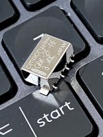
That might be a good relay, but the datasheet doesn't say anything about the contact material. In other Omron G6K family relay datasheets they do give some info on contact material, seems odd they don't say for the RF version.
Also, I tried the non-RF version of those relays for clock switching and they seem to work okay, at least in the short term. They were laid out in such a way that shielding was not required.
Last edited:
If I understand correctly FIFOPi needs 5MHz clock to play 44. To play Doede's 176.4 he needs at least a 22MHz clock regardless of clock brand. Many ways to get to 22MHz. For some who are complaining about price and complexity I suggest that dropping back slightly from best possible jitter is a path that may not produce an appreciable drop in listening pleasure.
I tried the non-RF version of those relays for clock switching and they seem to work okay, at least in the short term.
Just curious, how did you conclude "they seem to work okay", by listening? "Work okay" compared to what?
Ian,
That might be a good relay, but the datasheet doesn't say anything about the contact material. In other Omron G6K family relay datasheets they do give some info on contact material, seems odd they don't say for the RF version.
Also, I tried the non-RF version of those relays for clock switching and they seem to work okay, at least in the short term. They were laid out in such a way that shielding was not required.
@Markw4
SinePi will have three options for the on-board clock signal selector.
Should be flexible
")
A: No relay for FifoPi Q3
B: Standard relay for all FifoPi Q1,Q2 and Q3
C: RF relay for all FifoPi Q1,Q2 and Q3
Ian
If I understand correctly FIFOPi needs 5MHz clock to play 44. .
And with simultaneous mode applied to the TDA1541A ? I don't know if that applies to the Ian's I2StoPCM board with the TDA1451A in simultaneous mode but I confirm it does with Rogic's board ! I don't know if what you use with sim mode allows it though ?
Assuming most are using Andrea's SC-CUT with FifoPi :
In simultaneous mode with the TDA1541A, with 5 & 6 Mhz xtals you should read up to 88 and 96 K hz sampled materials and for the speed after the use of the second pad for 192K Hz with a 12 Mhz Xtal is still possible ! The TDA1541 is able to 384 sampling materials in sim mode.
I'm not sure the I2StoPCM converter is very proof to this with the 1541 due to the problem already talked on Diyaudio with this board and the entire compatibility with the simultaneous mode due to some programation errors of the software for the TDA1541 only. But at least he USB to Sim mode of Audial is working like that and at least should have sma connectors for Mori's clock, at least I asked for them and have hope to see them in the brandnew AYA 5 Diy board. I don't know about RyanJ sim board as his work doesn't interest me, but being from John ECDESIGN work, it should work.
The FifoPi is allowing such dual speed mode : one pad area with a 5.xx as you do, and the second for the rare materials that are 96 K hz or 192 K Hz with a 12.xx xtal on the second FifoPi pad.
So you should have not to make sacrifice too much with crystal speeds and as you know btw, the most is always about the power supply, the decoupling...
I have built the I2StoPCM board from RyanJ with his D3 dac board for the TDA1541A. I also have a dddac.
Both are fed with rpi/usbridge sig.-fifopi Q3-reclockpi. Clocks are the new Andrea Drixo SC-cut 5-6mhz with one doubler (I still have to solder the other 2) or 22-24mhz.
Both dacs play max. 44,1 with 5mhz, 88,2 with one doubler and 176khz with 22mhz clock.
I do not know how you archive 88,2 from 5mhz clock, can you please explain?
Pedja also selects 22-24mhz clocks for sample rates up to 192khz.
PS. I will also buy the new diy board from Pedja to see what this is all about (interesting to learn how different approaches turn out)
PPS. You should gain some interest in the designs of RyanJ, they have some very nice features. The I2StoPCM is from ECdesigns and his D3 board has some nice stuff like the input attenuators. The only thing that is bugging me on the D3 is the use of LM317.
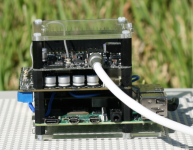
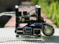
Portable/Transportable Project 95% Complete!
@InspectorGadget, Yay I found a use for the A123 26650 w/ tabs.
@iancanada, Thanks for making my portable/transportable optical transport dreams come true.
My vision was for a pocket-able optical transport powered by an A123 26650 with a audiophile OS.
I still have work to do. I need to wait for an RPi 4A/A+ or RPi 5A/A+ to potentially make this pocketable. With the hardware limitation of just RPi 4, it's just transportable for now.
I don't think a ReClockPi is in the mix since it makes it too tall. Too large a footprint. With a "Pulsar" clock, I may have no choice if I go with a normal sized "Pulsar" or a low-profile "Pulsar". Maybe if a Q4 is a combined Q3 + RCP, I can move that to this project and my current Q3 to the desktop.
I'm running AudioLinux:
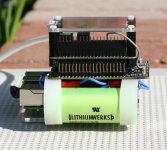
EDIT: Eventually, I plan to add black heat shrink around the battery so it looks more stealth. It sound goods without an Audiophile OS, but with an Audiophile OS it's sublime especially with tracks and OS loaded into RAM. With the A123 26650, it seems to give it weight and more punch (oomph). Could also be because it's straight from the battery (tabs) versus battery holder. #Ready4Pulsar
Now that this project is over and I literally just received Andrea's clock, I can focus on the desktop side.
@InspectorGadget, Yay I found a use for the A123 26650 w/ tabs.
@iancanada, Thanks for making my portable/transportable optical transport dreams come true.
My vision was for a pocket-able optical transport powered by an A123 26650 with a audiophile OS.
I still have work to do. I need to wait for an RPi 4A/A+ or RPi 5A/A+ to potentially make this pocketable. With the hardware limitation of just RPi 4, it's just transportable for now.
I don't think a ReClockPi is in the mix since it makes it too tall. Too large a footprint. With a "Pulsar" clock, I may have no choice if I go with a normal sized "Pulsar" or a low-profile "Pulsar". Maybe if a Q4 is a combined Q3 + RCP, I can move that to this project and my current Q3 to the desktop.
I'm running AudioLinux:
- Boot Mode: Normal
- Realtime Kernel
- Realtime Priority: Extreme
- Realtime Apps: Extreme
- Isolated Cores: 1st Core: System tasks. All other dedicated Cores just for Audio
- RamRoot: 4GB to load the whole OS into RAM
- Squeezelite 4GB buffer
EDIT: Eventually, I plan to add black heat shrink around the battery so it looks more stealth. It sound goods without an Audiophile OS, but with an Audiophile OS it's sublime especially with tracks and OS loaded into RAM. With the A123 26650, it seems to give it weight and more punch (oomph). Could also be because it's straight from the battery (tabs) versus battery holder. #Ready4Pulsar
Now that this project is over and I literally just received Andrea's clock, I can focus on the desktop side.
Attachments
Last edited:
@Supersurfer : my understanding is Rogic achieves up to 384 is sim mode with 22 Mhz xtal, 192 is with 12 Mhz xtals. Look at the last exchanges in the interest poll where you posted.
My understanding is John had given up at the end the attenuation inputs in front of the TDA1541A... Trade-offs. I personally use both I2S and sim mode but with Ian's I2StoPCM board that has not exactly the right setup for the sim mode with the TDA. It works but not at its best... I like the fact it is slavered by the Masterclock though.
Still have the FIFO Pi gen 1... Dunno what is better with the next gens ?!
Last edited:
I need to wait for an RPi 4A/A+ or RPi 5A/A+ to potentially make this pocketable.
The RPi Compute Module 4 with a custom board could be a way toward minimization in your case. CM4 has an eMMC option too. Kicad files for the official CM4 IO board are available, making a custom board design much easier.
@InspectorGadget, Yay I found a use for the A123 26650 w/ tabs.
@iancanada, Thanks for making my portable/transportable optical transport dreams come true.
My vision was for a pocket-able optical transport powered by an A123 26650 with a audiophile OS.
I still have work to do. I need to wait for an RPi 4A/A+ or RPi 5A/A+ to potentially make this pocketable. With the hardware limitation of just RPi 4, it's just transportable for now.
I don't think a ReClockPi is in the mix since it makes it too tall. Too large a footprint. With a "Pulsar" clock, I may have no choice if I go with a normal sized "Pulsar" or a low-profile "Pulsar". Maybe if a Q4 is a combined Q3 + RCP, I can move that to this project and my current Q3 to the desktop.
I'm running AudioLinux:
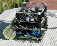
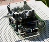
I plan to add a German OLED, not a mass produced OLED beneath the top plastic that's why there's open space up top and not tight. It will have an IR receiver for remote control. Unsure if I can fit it a control knob to select music. No room left.
- Boot Mode: Normal
- Realtime Kernel
- Realtime Priority: Extreme
- Realtime Apps: Extreme
- Isolated Cores: 1st Core: System tasks. All other dedicated Cores just for Audio
- RamRoot: 4GB to load the whole OS into RAM
- Squeezelite 4GB buffer
EDIT: Eventually, I plan to add black heat shrink around the battery so it looks more stealth. It sound goods without an Audiophile OS, but with an Audiophile OS it's sublime especially with tracks and OS loaded into RAM. With the A123 26650, it seems to give it weight and more punch (oomph). Could also be because it's straight from the battery (tabs) versus battery holder. #Ready4Pulsar
Now that this project is over and I literally just received Andrea's clock, I can focus on the desktop side.
That's nice. The I2S from the Toslink board still share its ground via the uf-L cable from the beneath board (FIFO Pi?) ? No isolation there as not needed, i.e. naturally made by the Toslink ?
What about the oled design made by John from ECDESIGN ? Cab it be superseeded on that ?
The compact size with the A123 is very cool
.@A123
Amazing project. Looks very nice. You use the LifePO4 battery cell in a very smart way.
Congratulations!
Ian
Thanks, it means a lot. Without the flexibility of your products, it would not be possible. I forgot to mention the flexibility of clock / oscillator rolling which is most important as no other products offer this solution. This allows me to be happy with my current setup, but the door is open to upgrade down the road when I'm ready or if new clocks are released. So basically, it's worth pursuing a project as you can scale over time.
@A123 How did you charge the 26650 battery cell?
Ian
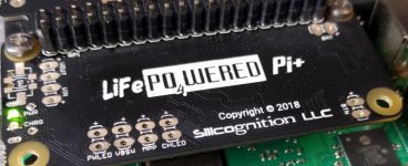
It's quite straightforward, the BMS handles all these tasks (See Attachments). On the side there is a micro USB port for charging next to the power switch.
Once I solder the battery wires to BAT, the BMS will handle the charging from there...
Other options include:BAT:
Battery voltage. This is where the user connects their external 1S LiFePO4 battery pack when the “no on-board battery” option was chosen. The “+” mark indicates the positive terminal.
It is recommended to have a high-current connector in the battery leads, so the wires can be soldered to the board without the actual battery connected. If this is not possible, be very careful to not short the battery terminals while soldering the wires to the board.
If the LiFePO4wered/Pi+TM does come with a battery on board, these connections provide direct access to the battery voltage. It is not recommended to connect any load to these pads because they are directly connected to the battery and as such provide no short circuit or over-discharge protection.
I use this to power the clock side:VOUT:
Output voltage. This is the switched 5 V output voltage to the Raspberry Pi. The “+” mark indicates the positive terminal.
A user can power other 5 V loads from these pads and they will be switched on and off together with the Raspberry Pi. For example, a case fan can be connected here.
You can use another power source to charge if you don't want to use micro USB:VBSW:
Switched battery voltage. This is an auxiliary switched output of the battery voltage (3.2 V nominal). The “+” mark indicates the positive terminal.
External 3.3 V circuitry can be powered from these pads and it will be switched on and off together with the Raspberry Pi. Unlike the BAT connections, this output has short circuit and over-discharge protection.
VIN: Input voltage. This is where the user can permanently connect the input power source instead of using the micro USB connector. The “+” mark indicates the positive terminal. Note that these are directly connected to the micro USB connector pins, so the USB input voltage can be measured here if the micro USB is used as power input. You should only ever use one of them at a time: either the micro USB or these pads.
It is recommended to use these pads instead of the micro USB in high power systems, since micro USB connectors were not designed to handle high currents.
I believe this one is for solar charging..BTN: External button. This is where the user can connect an external momentary switch to duplicate the functionality of the on-board push button. The “+” mark indicates the positive terminal (polarity is important if using a transistor instead of mechanical switch).
If the LiFePO4wered/Pi+TM is switched to touch pad mode, a capacitive touch pad can be connected to the pad marked with “+” and the other pad is not used. Keep wiring as short as possible in touch pad mode.
MPP: Maximum Power Point setting. This connection will allow the user to customize the maximum power point (MPP) voltage by adding a resistor across the pads. The charger will reduce the charge current as needed to ensure the input voltage does not drop below the MPP voltage. The “+” mark indicates the positive terminal.
By default the MPP voltage is 4.66 V nominal. This is what limits the input current so a weak USB port does not get overloaded. If the user connects a solar panel as input source, a resistor needs to be added to optimize for the panel’s MPP voltage.
The MPP resistor value can be calculated with the following formula:
RMPP = 51815 / (VMPP – 4.66)
Attachments

Last edited:
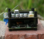
The RPi Compute Module 4 with a custom board could be a way toward minimization in your case. CM4 has an eMMC option too. Kicad files for the official CM4 IO board are available, making a custom board design much easier.
I'm in no rush as this is a pandemic build. Once things are back to normal, then hopefully I can downsize in 2022.
The CM4 would be a great option w/ eMMC since there is a 8GB model too, but I don't want to use a third-party board. It has to be an official RPi. As shown in the attachment the A models fit perfectly, I just need the modern 8GB. But I'll look into the custom board design route when I start giving up hope for new RPi A models. Thanks for the tip. I was following SBC gaming rigs, but haven't kept up with the latest boards so if there is something official out there I would consider.
I boot the RPi with USB so the eMMC would be great. eMMC is suppose to be super quiet with better performance. I have the option to remove the USB drive before I start a listening session after the OS boots into RAM, but that gets tiresome.
Attachments
Last edited:
- Home
- Source & Line
- Digital Line Level
- Asynchronous I2S FIFO project, an ultimate weapon to fight the jitter