The set-up as it is in the drawing is open-loop. Note that I use a pulse generator (that behaves like a AC source for freq. domain analysis) as the input to the FB network, while attaching the input to GND. This way I can see both the freq. response (AC analysis) and the transient (ringing, etc) with a single source.
BTW: Shielding the feeback can be a good idea.
Kenshin: about TIM caused by hi freq switching, it seems strange to me that distortion was slightly better (by eye) when nfb was taken before filter, as the bare switching waveform is there, and that should enworse things instead.
Cheers,
Pierre
BTW: Shielding the feeback can be a good idea.
Kenshin: about TIM caused by hi freq switching, it seems strange to me that distortion was slightly better (by eye) when nfb was taken before filter, as the bare switching waveform is there, and that should enworse things instead.
Cheers,
Pierre
Pierre:
I'm not proposing that the model is not suitable by principle--on the countrary, I meant that you can optimize the feedback like a linear lead-lag compensation.
about how much THD will be caused by the switching nature--I have really no idea.
about TIM:
you said that feedback directly from the switching stage has relatively low THD. This may because you are using only resistor in feedback. When connecting NFB from the total output, a capicitor is paralleled to generate a positive phase shift.The resistance of the cap at high frequency is very small,so the EMI spikes can flow directly into the OP AMP and cause TIM.
try serial a small resistor with the capicitor to suppress the high frequency noise.
Pierre said:BTW: All my simulations results are from a linear model of the amp, with no switching at all. I think I have said so before, but just in case we are leading to some confusion or the model is not suitable by principle. Kershin, is that what you propose?
I understand what Charles says about having constant NFB gain or higher at low frequencies. It is a matter of testing which of them gives better results.
See my sim. model in the attached figure.
Thanks , I will try.
Of course, the simulations are excellent, before and now, yielding distortions in the order of 4.5e-7 %, the problem, as always, is real life!
The fb. resistor is 68k and the cap is 56pF. A resistor of 2.2k in series is enough? Following the simulations, if I go higher, the freq. response deteriorates or is made more dependent on the load.
Best regards
Pierre
Perhaps it is the same thing to add a resistor in series with the R||C. What about 2.2k + (68k || 56pF) ?
This way, at low freqs, you have a feedback resistor of 70.2k, while at high freqs, the cap. is not directly bypassing all the EMI to the opamp. But... is 2.2k enough?
Pierre
This way, at low freqs, you have a feedback resistor of 70.2k, while at high freqs, the cap. is not directly bypassing all the EMI to the opamp. But... is 2.2k enough?
Pierre
56pf, 2.2k...the cutting off frequency is 1.29MHz,above the switching frequency. so it seems available.
A larger resistor up to 6.8K may also be available,now the pole is at 418 KHz.
if you use two poles at this frequency cascaded to produce enogh phaseshift( of course,the phaseshift of output LPF is considered) and ensure reliable oscillation,it may become a good self-oscillating one.
A larger resistor up to 6.8K may also be available,now the pole is at 418 KHz.
if you use two poles at this frequency cascaded to produce enogh phaseshift( of course,the phaseshift of output LPF is considered) and ensure reliable oscillation,it may become a good self-oscillating one.
Pierre said:Thanks , I will try.
Of course, the simulations are excellent, before and now, yielding distortions in the order of 4.5e-7 %, the problem, as always, is real life!
The fb. resistor is 68k and the cap is 56pF. A resistor of 2.2k in series is enough? Following the simulations, if I go higher, the freq. response deteriorates or is made more dependent on the load.
Best regards
Pierre
Let's see how far can we get before I leave...
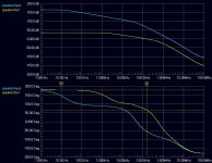
Well: that's the open loop simulation with the following values:
Series fb resistor: 4.7k
Comp. network: 68k || 56pF
Integrator: 220k || (10k+330pF)
With this setup, the feedback -3dB bandwidth is 2K, and phase margin is about 60 degs. However, I can get a wider feedback bandwidth (althogh less open loop gain) by reducing 220k to, say, 100k and 330pF to, say, 100pF.
Closing the loop, seems right, at least as before.
Charles, do you agree with Kenshin in that the series resistor can help reducing EMI in the integrator and that this can be the cause? Seems sensible, isn't it? (you don't seem to be pleased with the idea...)
Attachments
Charles, do you agree with Kenshin in that the series resistor can help reducing EMI in the integrator and that this can be the cause? Seems sensible, isn't it? (you don't seem to be pleased with the idea...)
UCD does it.
Mind if I ask what program that came from?? Has a nice look to it.
Charles, do you agree with Kenshin in that the series resistor can help reducing EMI in the integrator and that this can be the cause? Seems sensible, isn't it? (you don't seem to be pleased with the idea...)
From:
http://www.diyaudio.com/forums/showthread.php?postid=534362#post534362
One does not necessarily need to differentiate the feedback signal up to infinity. One can play with a series resistor on the capacitor of the feedback branch that is between 1 and 10% of the NFB resistor's value. That's another option I would suggest to Pierre to try out.
Regards
Charles
Thanks for your soons responses today!
But UcD is based on a completely different concept, it is self oscillating, indeed.
I use Protel for my boards, captures and simulations, it is a very complete package.
A bit more info: The difference in open loop response with 10k series resistor vs. without it is:
0dB point: 140KHz (10k resistor) vs. 176KHz (no resistor).
Phase margin: 58.6º vs. 77º
Response at 275KHz: -8dB vs. -3.6dB
So the only benefit is a <5dB attenuation more at the sw. frequency, will that be really noticeable?
Cheers!
This phase-marging of around 60 degrees is not world-record but there is rumours that there are linear amps with only 45 degrees of phase marging.
As long as we still have approx the same frequency response up to about 100 kHz we will be fine IMO.
You mention that we only decrease the level by about 6 dB at the switching frequency. This is true, but don't forget that it is much more for the higher spectral content of the switching waveform, which is where the op-amps are challenged and where transient overshoot etc is located.
Regards
Charles
my Simpw has only poles on the real axis -- does that means the phase margin is bigger than 90 degrees?
phase_accurate said:This phase-marging of around 60 degrees is not world-record but there is rumours that there are linear amps with only 45 degrees of phase marging.
As long as we still have approx the same frequency response up to about 100 kHz we will be fine IMO.
You mention that we only decrease the level by about 6 dB at the switching frequency. This is true, but don't forget that it is much more for the higher spectral content of the switching waveform, which is where the op-amps are challenged and where transient overshoot etc is located.
Regards
Charles
For me - being an audiohead - it is much simpler to look at the bode diagram (I don't like pole-zero diagrams).
Are you talking about Pierre's circuit BTW ? At least the output filter should cause a complex pole-pair as a quick shot from the hip.
We could of course completely eliminate their effect by the use of a transfer function of the form
s^T^2 + sT/Q + 1
So we actually hopped into the thread "creating a positive phase-shift".
Regards
Charles
Sorry for not reading the entire thread before posting.
My experience with triwave classd is that switch ripple fed back from the output is very bad for THD. This means that a zero as the one you have introduced is causing THD at the same time as it is increasing phase margin.
My solution was to apply a series notch filter in paralell with the filter capacitor. For example using a 3uH coil, 220nF cap and 0,1ohm resistor gave med 14dB attenuation at 200kHz. This makes it possible to lower the filter caps in the output filter at the same time as it decreases the ripple in the feedback loop enabling the use of a zero in the feedback path. A tip is also to have a resistor in series with the zero in order to limit the bandwidth of the zero and the ripple at the switching frequency.
Ok, see what you mean. No problem.
I will try a simulation.
I have tried a similar notch setup in practice, I think someone in the forum suggested that some time ago: a second stage LC filter (outside the loop), with a capacitor and a resistor in parallel with the inductance. That works very well in reducing the switching residue, but can't be included in the feedback loop easily.
Does the coil need to be rated at the output current?
Thanks
This means that a zero as the one you have introduced is causing THD at the same time as it is increasing phase margin.
It won't do that to a higher degree than taking NFB from the switching stage directly and using an ordinary integrator.
The notch-filter aaproach does indeed look convincing from a first glimpse (I once built a class-d amp with a cauer filter and pre-filter NFB that had a carrier suppression of 80 dB !) but it worsens the phase-marging.
If the reduction of the main output filter cap is an advantage is debatable. An amp with a lower cap value will be more susceptible to capacitive loading for instance.
I once made simulations with a notch filter in the forward path of the amp, which should achieve the same advantage (but could be done without another inductor) but the results weren't convincing.
As an addition to the aforementioned series resistor an LPF could be used in the feedback branch further removing glitches.
Regards
Charles
Well, simulation done!
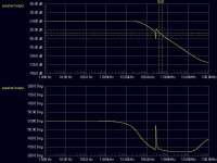
I see a big problem in that configuration: the filter shows a notch at the calculated frequency, BUT followed by a peak in its response in a very short frequency displacement, so you can move from a very good situation to a very bad one if the clock frequency moves a little bit, or if the tolerances of the clock or notch components vary sligthly.
Do you think that only the resistor in series with the zero is enough to make it work well?
This is what I get for the filter (only the filter) response with the notch filter proposed by Pabo (approx. values)
Attachments
- Status
- This old topic is closed. If you want to reopen this topic, contact a moderator using the "Report Post" button.
- Home
- Amplifiers
- Class D
- Help with feedback