A test with 220 ohms should be O.K. IMO.
In the meantime I checked the phase-gain plot of your NFB network and it didn't look bad.
Just out of curiosity: How do things change as soon as you increase the open-loop gain at the low end by increasing the parallel resistor of the integrator, like from 47 k to 150 k ?
Regards
Charles
In the meantime I checked the phase-gain plot of your NFB network and it didn't look bad.
Just out of curiosity: How do things change as soon as you increase the open-loop gain at the low end by increasing the parallel resistor of the integrator, like from 47 k to 150 k ?
Regards
Charles
😱
Ouch, I see you were posting while I still had the posting window open. That happens when one is slow with finishing posts !!!
Regarding your pictures I see two things (or do at least think so):
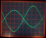
1.) there seems to be a small load-dependancy of the effect as the last output waveform is a little cleaner than the one with 2.65 Ohms load.
2.) even the input signal doesn't look totally clean.
To 1: This might be due to a ground-loop problem, i.e.differential feedback would help in this case. How does your ground look BTW, is it a ground-plane ? Or it could also be due to the changeing properties due to the different output filter damping. Maybe it would be beneficial to increase the phase-marging, I will do some brainstorming on this.
To 2: What is your signal source ? How does the sinusoidal look like if the amp isn't running and nothing else than the scope is connected to the source ?
Regards
Charles
Ouch, I see you were posting while I still had the posting window open. That happens when one is slow with finishing posts !!!
Regarding your pictures I see two things (or do at least think so):
1.) there seems to be a small load-dependancy of the effect as the last output waveform is a little cleaner than the one with 2.65 Ohms load.
2.) even the input signal doesn't look totally clean.
To 1: This might be due to a ground-loop problem, i.e.differential feedback would help in this case. How does your ground look BTW, is it a ground-plane ? Or it could also be due to the changeing properties due to the different output filter damping. Maybe it would be beneficial to increase the phase-marging, I will do some brainstorming on this.
To 2: What is your signal source ? How does the sinusoidal look like if the amp isn't running and nothing else than the scope is connected to the source ?
Regards
Charles
My source isn't definitively too good. It is a function generator I built at least 8 years ago, based on a ICL8038, so you can imagine! I will post some photos of the waveform with the generator and oscilloscope alone for you to see it, but I am sure that its THD is no better than 0.1%.
Now that things are better I will try to use my work's generator, a much better HP, or at least a PC with a good soundcard.
Yes, there is a little dependency on the load, but have in mind that we are comparing 170W versus 1.36W!
I will try also your suggestion about increasing the resistor from 47k to 150k.
Thanks, and please don't spend too much of your time on me, that's not fair!
Pierre
Hi,
I have to say, sorry for posting this!
Have you simulated this, in particular, the change from pre to post filter feedback? If you can that might really help to rule out alot of things, like EMI RFI situations, spice doesn't do that, and if you see the same kind of distortion changes after going post filter feedback in spice, we know we have to look someplace else, and you'll be able to rip through the simulation alot quicker than with the real circuit to weed out any oversights.
Also, instead of just going with a slow test signal, (less than 1 HZ was mentioned) why not just use DC with a pot?
Thanks
No need for being sorry.
In a simulation (using ideal elements) the circuit behaved well, with THD below 0.1 %. It does show some ultrasonic hash between 20 kHz and 150 kHz though.
You can of course also do a DC sweep with a pot. I just suggested the slow AC signal because I by myself would do it like that out of lazyness !
Regards
Charles
Hi,
I had to say sorry as I figured the questions I asked were already answered up in the thread someplace and I just had to read it.
That's funny because I would have been tempted to use DC out of lazyness🙂
Ultrasonic hash? Not sure .. what would that look like, extra residual ripple?
Maybe if that's the case once we throw some real world components in it no longer remains ultrasonic?
It shouldnt' be too hard to add some parasitics into the simulation and find out how it could twist things around, (you probably have a good idea how it would already, but I don't) add some ESR in the filter components, some ESL and parallel capacitance for the resistors involved, might very well bring that hash down to 10Khz yeh?
If that's the case how would you fix that, different values or better parts, of course no parts are ideal but some are better than others, this could be a really good reason why the pro's insist on SMD and double layer boards.
I've read that some types of resistors start looking like caps at 50Khz~100Khz..
RANT: You know in this day and age with the PC's we've got such parasitics should really be included in spice already, at least for the passive components, especially when you consider the kind of price tag most of these come with.
Anyway, this is really the "proper" use for spice, try to get it to replicate what the real world circuit is doing and it should give a good indication how to cure it. What a pain though
Hmmmm, to that end, maybe we could add what the scope probes might be doing to it in the simulator as well.
Thanks for your patience 🙂
Well, I will try to start constructing a proper model of the circuit, although I am afraid that reproducing the same effects I have observed will be quite difficult, as all the layout parasitics should be included as well, not only the components non-idealities.
Meanwhile, I think it still worths the pain to play a bit more with the circuit, anyway.
Thanks for your help and happy new year!
I will keep you posted.
Meanwhile, I think it still worths the pain to play a bit more with the circuit, anyway.
Thanks for your help and happy new year!
I will keep you posted.
Although this is not related to the issue of this thread, I am a bit worried because last night one of my test amplifiers (that had NFB before filter, btw), failed in a party. The output devices got shorted causing the PSU fuses to blow.
I use 150V mosfets with a +/-45V supply, and the drive circuit is a quite typical IR2113, with some dead-time, the PWM waveform looks good... I don't think the failure was unchained due to overcurrent, as it was playing very good and quite cool for hours with music, with much less demanded power than the lab tests. (about 100W peaks).
Perhaps a spike in the gate caused one of them to fail, what produced a failure in the other due to overcurrent? Should I put a 15v zener in parallel with Vgs?
My mosfets are OnSemi's NTP35N15, following the suggestion of someone in the thread.
Any other possible cause of failure of the mosfets, from your experience, like uncontrolled spikes from the output coil, or whatever?
Thanks!
Hello all.
I will be out for some days, but be sure that the thing is not forgotten! ;-)
When I am back, I will continue with the feedback network optimization, with your wise help, and let's see if I can post some measurements of THD, etc, also.
Best regards,
Pierre
I will be out for some days, but be sure that the thing is not forgotten! ;-)
When I am back, I will continue with the feedback network optimization, with your wise help, and let's see if I can post some measurements of THD, etc, also.
Best regards,
Pierre
mmm.
One question more before leaving:
When I simulate the circuit open loop (disconnect the feedback takeoff from the output, input to gnd, and test signal at the feedback takeoff), we spoke about measuring the phase marging by measuring the phase when the gain of that is 0dB, right?
And what about the -3dB bandwidth? Shouldn't it be the whole 20KHz audio band?
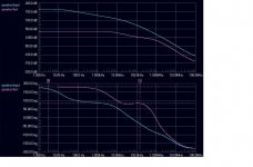
With the values Charles suggested me, the open loop transfer function has a DC gain of about 22dB, and a -3dB point at about 8KHz. Is that enough?
If I increased the integrator parallel resistor from 47k and lower the integrator cap, I can get 36dB of gain with -3dB at about 5.5KHz.
For example, the image shows what I get with 10k+150p || 220k in the integrator, and 68k || 68p as feedback network. (22uH+440nF LC filter). Is this any better (theoretically)?
One question more before leaving:
When I simulate the circuit open loop (disconnect the feedback takeoff from the output, input to gnd, and test signal at the feedback takeoff), we spoke about measuring the phase marging by measuring the phase when the gain of that is 0dB, right?
And what about the -3dB bandwidth? Shouldn't it be the whole 20KHz audio band?
With the values Charles suggested me, the open loop transfer function has a DC gain of about 22dB, and a -3dB point at about 8KHz. Is that enough?
If I increased the integrator parallel resistor from 47k and lower the integrator cap, I can get 36dB of gain with -3dB at about 5.5KHz.
For example, the image shows what I get with 10k+150p || 220k in the integrator, and 68k || 68p as feedback network. (22uH+440nF LC filter). Is this any better (theoretically)?
Attachments
With the values Charles suggested me, the open loop transfer function has a DC gain of about 22dB, and a -3dB point at about 8KHz. Is that enough?
This is a question of taste. Some people prefer more NFB and a lower -3dB point of the open-loop gain. You can achieve this by incresing the parallel resistor of the integrator and leaving everything else untouched.
If I increased the integrator parallel resistor from 47k and lower the integrator cap, I can get 36dB of gain with -3dB at about 5.5KHz.
But now you have a unity-gain frequency of more than 1 MHz ! => Edit: I misinterpreted your diagram, forget about this statement !
Regarding the discussions of circuit non-idealities: I almost forgot that the output-filter itself might not behave like an ideal 2nd order filter due to inductance and capacitor losses. Is there any possibility for checking its response up to some MHz ?
Regards
Charles
Thanks for the fast response.
But at a given frequency, increasing NFB should reduce distortion, right?
About the filter measurements, yes, it is possible, I can use a network analyzer.
I suppose you mean the response of the filter loaded with, say, 4 ohms, right?
However, it is easier for me to check the components separately with a component analyzer. For example, magnitudes of inductance and series resistance for the coil, and capacitance and series resistance for the capacitor. Is that enough?
I can do the measurements but with small signal, so the saturation effects won't be seen.
However, I don't think the filter is the cause for the increase in distortion, as it is the same filter that I use for feedback BEFORE filter.
Best regards,
Pierre
Hi Pierre,
It might help if you found out what the self resonance frequency of your coil is, then you can deduce a value for parallel capacitance, even your resistors have some parallel capacitance and ESL. Depending what type of resistors you're using you should be able to look up those values easily enough.
I'd only concern myself with the feedback and filter components for this exercise, possibly even ESL / ESR of the wires themselves (best guess)... it only takes a few seconds right.
When you have the parasitics in you can quickly swap from pre filter to post filter feedback and see how it reacts.
Even if it shows little or no difference, we'll all learn something from it and it's well appreciated.
BTW are you using shielded wire for your feedback line (kind of hard to model that).
Regards
Pierre:why the error opamp is a integrator one?
when using feedback from the switching stage,a integrator is needed for lower down the high amplitude of switching (square)waveforms and change it into triangle.
but the LC filter's output signal is already filtered,why there's need for a integrator? Is it designed for "delay" mode phase compensation as in a (chip) OP AMP?
Pierre said:The error opamp (integrator) capacitor is 470pF, and a 100K resistor in parallel, to improve DC offset, etc.
But at a given frequency, increasing NFB should reduce distortion, right?
Yes, but sometimes people prefer to have almost constant NFB throughout the audio range in order to get constant THD over the audible frequency range. It is a matter of taste however.
I suppose you mean the response of the filter loaded with, say, 4 ohms, right?
Yes. Deviations from the 2nd order behaviour would mean that the loop would have to be redesigned. I am not talking about the range around cutoff but frequencies above. You have to take into account that the coil is behaving less like an inductor the higher you go with frequency (rising core losses, winding capacitance etc). Similar problems exist for the capacitor.
I can do the measurements but with small signal, so the saturation effects won't be seen.
That's O.K. in this case.
However, I don't think the filter is the cause for the increase in distortion, as it is the same filter that I use for feedback BEFORE filter.
Even though we try to decrease distortion by the post-filter NFB I could imagine that there are possibilities that the contrary may be caused.
But let's first sort out the frequency-domain problem.
BTW: What is the tech data of your inductor, apart from the inductance, which we already know ?
Regards
Charles
No, the feedback is taken with a track around the edge of the board to the integrator.
I will try to post the measurements of the components, better than just relying on the datasheets. I suspect that this is not the problem, however, but worths a try, as classD4sure points.
About the integrator, well, the design was first intended to take feedback from the switching stage, where it was needed. Then I played a bit myself, asked here and Charles suggested me the component values. The integrator limits the open loop gain at high frequencies, so it is 0dB at about half the sw. freq.
I tried to remove the cap and series resistor across the opamp (only a 100k resistor around it) and simulations are much worse (strong load dependency, ringing at low loads, small phase margin, etc).
Thanks and best regards.
Hi Pierre,
Have you done this on a PCB or Protoboard? If it is on a protoboard it may not be worth trying to model parasitics.
I have seen others (Charles for one) recommend taking feedback with coax when taking post filter feedback, with the shield grounded or terminated somehow, might be worth a shot too.
Have you done this on a PCB or Protoboard? If it is on a protoboard it may not be worth trying to model parasitics.
I have seen others (Charles for one) recommend taking feedback with coax when taking post filter feedback, with the shield grounded or terminated somehow, might be worth a shot too.
Pierre:
with the integrator, now it's a lag-lead compensation --something classical.
try to do it as in an classical (linear) lag-lead compensation system.
BTW:
a op amp -- either in the error amp or in triangle wave generator-- running at such a high ripple frequency,its internal frequency compensation network may generate some TIM. this may be the cause of some distortions.
No, for god's shake! It is not done on a proto-board! I did it in a double-sided handmade PCB.
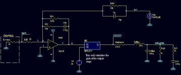
BTW: All my simulations results are from a linear model of the amp, with no switching at all. I think I have said so before, but just in case we are leading to some confusion or the model is not suitable by principle. Kershin, is that what you propose?
I understand what Charles says about having constant NFB gain or higher at low frequencies. It is a matter of testing which of them gives better results.
See my sim. model in the attached figure.
Attachments
- Status
- Not open for further replies.
- Home
- Amplifiers
- Class D
- Help with feedback