I've tried to build one of these, but i'm having problems trying to get it to start oscillating. Without load, it simply gets stuck (bootstrap led on - on a single halfbridge, no signal at output) With load (4-8ohms) it tries to oscillate, at about 800-900Khz but it either fails when an input signal is applied or simply by itself after some time. Trying to increase the capacitors in the feedback loop doesn't seem to affect it.
send HD pictures and schematic
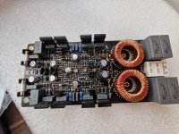
I've attached a photo of the board.
Since I had some problems with pcbway, they offered me some free stuff, so I got ahead and ordered a 6 layered matte black enig board . The pcb is my design, the schematic is the one the OP posted in the first post. A couple of small modifications were made:
- 2 pairs of IRFP4227 per halfbridge
- added some trim resistors to accurately set dead time.
The additional layers are used for power/gnd planes.
The output coils are T157-2 (Micrometals) about 50 turns each.
I've previously made the half bridge version of this schematic, that worked, I guess i'm missing something here.
Since I had some problems with pcbway, they offered me some free stuff, so I got ahead and ordered a 6 layered matte black enig board
. The pcb is my design, the schematic is the one the OP posted in the first post. A couple of small modifications were made: - 2 pairs of IRFP4227 per halfbridge
- added some trim resistors to accurately set dead time.
The additional layers are used for power/gnd planes.
The output coils are T157-2 (Micrometals) about 50 turns each.
I've previously made the half bridge version of this schematic, that worked, I guess i'm missing something here.
Attachments
Last edited:
I've attached a photo of the board.
Since I had some problems with pcbway, they offered me some free stuff, so I got ahead and ordered a 6 layered matte black enig board
- 2 pairs of IRFP4227 per halfbridge
- added some trim resistors to accurately set dead time.
The additional layers are used for power/gnd planes.
The output coils are T157-2 (Micrometals) about 50 turns each.
I've previously made the half bridge version of this schematic, that worked, I guess i'm missing something here.
Im shocked this is very poor PCB Design
Your design look like Class AB amplifier, this amp will not work stable or never !!!
You get verything what you dont want ! Parasitic Induction, Switching losses and so on
Please add schmatic from your PCB to compare latest design
Im shocked this is very poor PCB Design
Your design look like Class AB amplifier, this amp will not work stable or never !!!
You get verything what you dont want ! Parasitic Induction, Switching losses and so on
Please add schmatic from your PCB to compare latest design
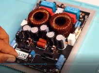
Fullbridge same schematic Working
look PIC and PCB Desigb
3000W Programm POWER
1800W RMS POWER
Attachments
this is a test pcb not intented to be used in a final product or God forsake, be sold.
It's one of my first class D designs made in a hurry not to catch the Chinese coronavirus situation.
I know it has it's flaws.
However, ucd designs will oscillate even when made on a breadboard with TH parts and jumpers, this should at least start.
I'm trying to figure how to troubleshoot it, given my lack of experience in class D or high speed switching circuits.
I don't intend to pull 500-1000-1800W from it.
At this moment I don't have access to the computer where my schematic was drawn, but basically it's the one in the first post of this thread with the modifications stated above. I tried to add a overcurrent protection (the same that was added in the half bridge design, with rail sensing and the 555 circuit) but on this board it is disabled (removed parts).
I'm trying to figure how to troubleshoot it, given my lack of experience in class D or high speed switching circuits.
I don't intend to pull 500-1000-1800W from it.
At this moment I don't have access to the computer where my schematic was drawn, but basically it's the one in the first post of this thread with the modifications stated above
It doesnt matter to get 1800W or 200W if PCB design have no flaws
If PCB Design have flaws also 100W will not working stable or never.
Lest start with your schematic, please post it.
My picture is exactly same schematic and amp which you have designed.
Lets check first for flaws in your schematic.
Finally, If you have no design flaws, its easy to get same output power
I can't get to the computer at work, since that place is in a shopping center under lockdown due to the epidemic.
I found a version of the schematic on my computer, I've attached a pdf of it. It has all the values of the components on the actual board.
The imput opamp is not a 5532 but a tl072 like in original schematic.
I found a version of the schematic on my computer, I've attached a pdf of it. It has all the values of the components on the actual board.
The imput opamp is not a 5532 but a tl072 like in original schematic.
Attachments
I can't get to the computer at work, since that place is in a shopping center under lockdown due to the epidemic.
I found a version of the schematic on my computer, I've attached a pdf of it. It has all the values of the components on the actual board.
The imput opamp is not a 5532 but a tl072 like in original schematic.
hi mbogdan and nmos thanks for sharing , how is the hf noise issue? is the layout silent? is the schematic correct ?
hi mbogdan and nmos thanks for sharing , how is the hf noise issue? is the layout silent? is the schematic correct ?
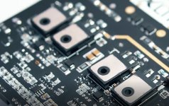
look my pics schematic is working
Fullbridge same schematic Working
look PIC and PCB Desigb
3000W Programm POWER
1800W RMS POWER
This yours NMOS? Looks great with good design! Could you share the PCB files?
This yours NMOS? Looks great with good design! Could you share the PCB files?
its not from me, i get from other people to share
hi mbogdan and nmos thanks for sharing , how is the hf noise issue? is the layout silent? is the schematic correct ?
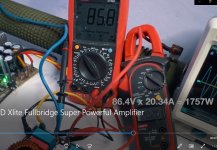
there is no noise stewin and very stable i have run +-88.7 vdc but not discrete version, kartino have 2 version of amp, full discrete another one is ir2110, so because i dont want too many component lol, so i do the ir2110 version one. This amp have perfect protection, dc, OCP, clip, signal, delay on. this is perfect design.

Hi Kartino, good day. What is the oscillation frequency on that design? Thank you.
i believe the fsw is 250khz.
there is no noise stewin and very stable i have run +-88.7 vdc but not discrete version, kartino have 2 version of amp, full discrete another one is ir2110, so because i dont want too many component lol, so i do the ir2110 version one. This amp have perfect protection, dc, OCP, clip, signal, delay on. this is perfect design.
View attachment 831349
Nice work Norazmi
Good to see you here also.
Your core 3.3cm single will allow output appx 400W max. Use double core will allow output up to 1000W easily.
Discrete version is UcD.
So actually it has very different color. Both are OK
i believe the fsw is 250khz.
For fullbride UcD Small mosfet can allow fsw 300-400kHz
I use IRFP4768 at speed 220kHz to get better switching efficiency, but it can get fsw up to 260kHz. Fsw set by adjust deadtime R or feedback cap.
I've attached a photo of the board.
Since I had some problems with pcbway, they offered me some free stuff, so I got ahead and ordered a 6 layered matte black enig board
- 2 pairs of IRFP4227 per halfbridge
- added some trim resistors to accurately set dead time.
The additional layers are used for power/gnd planes.
The output coils are T157-2 (Micrometals) about 50 turns each.
I've previously made the half bridge version of this schematic, that worked, I guess i'm missing something here.
Stewin, NVMOS is correct for your pcb review.
Try contact Wahyu Eko Romadhon. Mayne you can order sample so you can learn the correct pcn design.
He has youtube channel, and he post many his works based on my schematics.
- Home
- Amplifiers
- Class D
- UcD Xlite Fullbridge PCB and Schematic