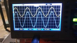
Crossover notch
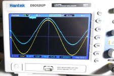
Is that the output of the amp we are looking at there? Left and Right channels.
Yes it is. Frequency was 1Khz and I believe that pic was "zoomed in" at 2v/division.
Input signal was set at ~ 500mv
8 ohm dummy load on both channels.
I used 2 sources....the first was an old Trio signal generator and for the second I used a function generator app by Kewlsoft on my android phone. The later only provided about 300mv output but showed the same results. I'll try to redo the test scoping both input & output, one channel at a time and take a few more pics.
I should add that this is my first scope and I'm still learning with it.
I don't know if it makes a difference or not but the pic was taken with the klipper disabled.
The klipper could not introduce distortion like as far as I can see. It might be worth trying with no load as well and seeing if the distortion goes.
Are there such things as fake LM3886's? as I can't really think of anything else that could generate a non linearity like that.
Is it all built on a proper PCB with proper return of the load currents back to the power supply?
Very odd.
Are there such things as fake LM3886's? as I can't really think of anything else that could generate a non linearity like that.
Is it all built on a proper PCB with proper return of the load currents back to the power supply?
Very odd.
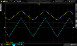
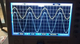
More scope shots
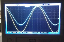
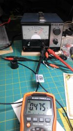
For these pics I only used the Trio signal generator as I needed the phone to take the pics. Pay no attention to the date on the scope screen as it is not set correctly.
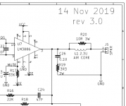
Amp was built exactly as specified in Mark's schematic & BOM using Mark's boards. Parts were purchased from Mouser & Digikey. In both scope shots, the yellow trace is the input and the blue is the output into the 8 ohm load. first up is the left channel followed by the right. 3rd pic is a pic of the trio and the signals voltage level taken at the Trio's output. I ran the self calibration of the scope and did a check of both probes before starting.
did the tests with the volume pot wide open. When I get a chance should I repeat the test without a load?
For these pics I only used the Trio signal generator as I needed the phone to take the pics. Pay no attention to the date on the scope screen as it is not set correctly.
Amp was built exactly as specified in Mark's schematic & BOM using Mark's boards. Parts were purchased from Mouser & Digikey. In both scope shots, the yellow trace is the input and the blue is the output into the 8 ohm load. first up is the left channel followed by the right. 3rd pic is a pic of the trio and the signals voltage level taken at the Trio's output. I ran the self calibration of the scope and did a check of both probes before starting.
did the tests with the volume pot wide open. When I get a chance should I repeat the test without a load?
Attachments
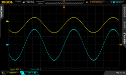
I powered up the Super Gain Clone stereo amp shown in photo #3 of the very first post in this discussion thread. I told the oscilloscope to make screen-capture-png image files; in each case the input is on top, in yellow; and the output is at bottom, in blue.
You can see that the amplifier's input-to-output gain is almost 20X, except for resistor tolerances in the amp and, I expect more importantly, scope A-to-D quantization and waveform feature extraction tolerances in the scope itself.
The first screen grab shows a 1 kilohertz sinewave, the second shows a 1 kilohertz triangle wave, and the third shows a 20 kilohertz sinewave. They all look reasonable to me.
_
Attachments
When I get a chance should I repeat the test without a load?
It would be interesting to see it without a load and also perhaps at a little higher frequency, even 10kHz.
Keep the output lowish in voltage swing as that shows the distortion more clearly.
You could also see if going to 4 ohm load (the amp will be fine with that at low levels) makes it much worse.
It is really really strange and I can't see how even a wiring error (ground returns) could cause anything like that.
Also check that the signal is clean at the point the klipper connects which is the D4/D5 junction. That would show the input to the chip is good or not.
Check also that there is no appreciable signal present on the servo chip output. There will be a DC voltage there (so use AC coupling) but the signal should be pretty much non existent, perhaps just a few millivolts pk/pk.
A bad solder joint, or a failed component, or a poor mounting on the heatsink, would affect one channel but not both. So it's surprising that this problem manifests on both channels.
Post #205 says "with the volume pot wide open" ... but the Super Gain Clone doesn't have a volume pot. I wonder whether part of the issue might possibly be, this mystery potentiometer?
Post #205 says "with the volume pot wide open" ... but the Super Gain Clone doesn't have a volume pot. I wonder whether part of the issue might possibly be, this mystery potentiometer?
Post #205 says "with the volume pot wide open" ... but the Super Gain Clone doesn't have a volume pot. I wonder whether part of the issue might possibly be, this mystery potentiometer?[/QUOTE]
This "mystery" pot is a 50k Alps blue pot. When I run additional checks later today I could bypass the pot to see if that helps.
Mooly suggested the following checks and I'll do these as well.
It would be interesting to see it without a load and also perhaps at a little higher frequency, even 10kHz.
Keep the output lowish in voltage swing as that shows the distortion more clearly.
You could also see if going to 4 ohm load (the amp will be fine with that at low levels) makes it much worse.
It is really really strange and I can't see how even a wiring error (ground returns) could cause anything like that.
Also check that the signal is clean at the point the klipper connects which is the D4/D5 junction. That would show the input to the chip is good or not.
Check also that there is no appreciable signal present on the servo chip output. There will be a DC voltage there (so use AC coupling) but the signal should be pretty much non existent, perhaps just a few millivolts pk/pk.
YES!
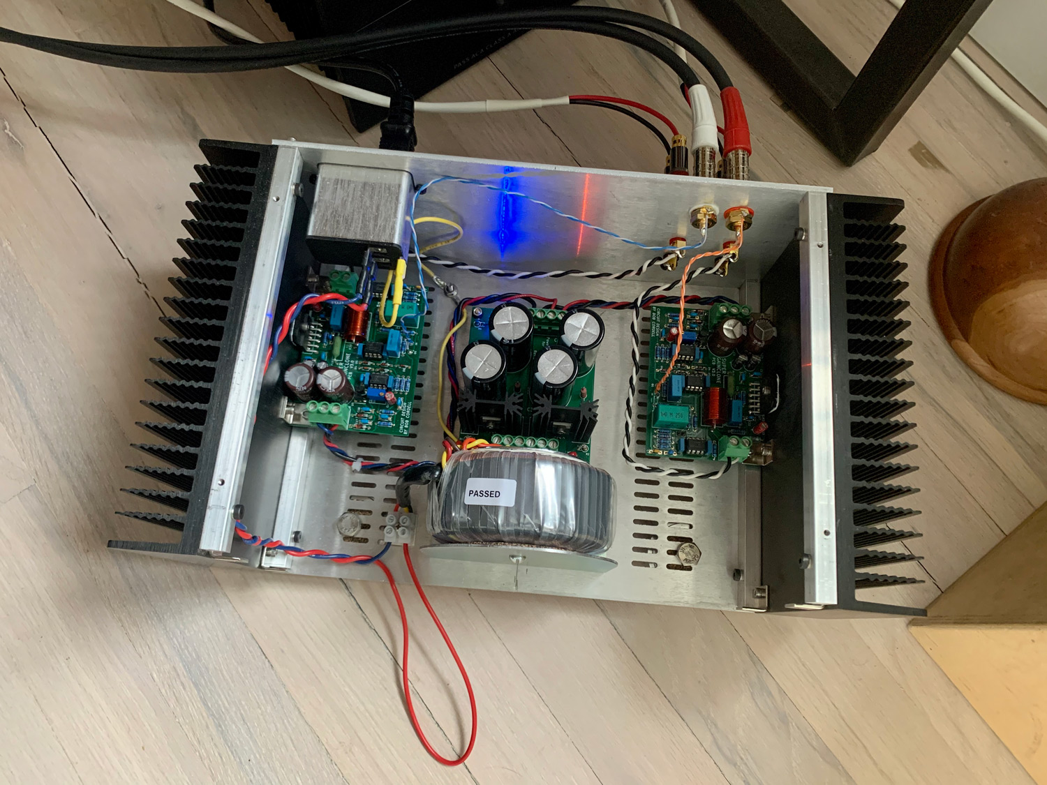
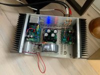
Couldn't wait to finish it completely. Sounds FANTASTIC with Noir in front. And I love the weeny proportions I ended up with in terms of physical amp size (built around a pair of 3U sinks from Modushop I had laying about.—Likely WAY overkill, I can't really feel any heat on them...been running for an hour—I think you could build this with internal sinks).
I did make this amp concurrent with a some M2X mono blocks. It's been fascinating to A/B them in the shop. I plugged earbuds directly into the speaker jacks with the inputs shorted. Was able to tune the transfo—huge difference—also got quieter with the lid on. And could hear the left has a bit more "noise/buzz" than right—longer AC? routing... overall it's not HUM—just some "hush". I was testing it with the B1K in the shop—that does have some noise in my main system—silent with no ringing with the M2X mono blocks—slightly ringing and some noise is back with Cordell—ground loop with B1K? Monoblocks difference? The M2Xs are absolute ghosts. Incredible. Anyway—I can't hear any buzz or hum with the Cordell and some B+W speaks with Noir—Tidal on the Mac as source (I will check again later since we do have a fair amount of ambient noise in the studio). Great bass (like I can feel it in my feet)—good all around really. VERY very pleased.
Also, there's a different sound profile between 3886 and all the other Pass amps I've made so far...hard to describe. It's a "refinement" thing. More "music" with the Pass designs maybe—but no difference in listenability. Cordell is sticking around. I do prefer it to the mono ACAs it's sitting in for in the office..... ah... there I said it! (My Opinion).
I have the Klipper disabled til I can figure out if the device I have in the shop that my uncle sent me is a signal generator or not (Stanford Research Systems DS360 Ultra Low Distortion Function Generator) Need to read the manual—and it needs probes. I'd rather do the full Klipper setup as opposed to the no scope version.
Yea! Mark Johnson. Thank you! (and Cordell too of course. Ha!)
I'll post a finished pic after I make the front.
Attachments
Beautiful and compact! Congratulations Patrick! If you decide to trim about 8 inches from that bottom orange loopy wire, even better still. (Unless it's needed for a front panel on/off switch that we haven't seen yet ...)
I'm sure with 3U tall heatsinks, that amp will never get warm.
edit- please feel free to paint over the Power OK LEDs on the PSU board if their glow annoys you, squirting out of the chassis vent holes. You can either use 100% opaque, or some type partial filtering ... diluted nail polish?
I'm sure with 3U tall heatsinks, that amp will never get warm.
edit- please feel free to paint over the Power OK LEDs on the PSU board if their glow annoys you, squirting out of the chassis vent holes. You can either use 100% opaque, or some type partial filtering ... diluted nail polish?
Last edited:
4R & No load pics
Mooly,
Sorry this took two days but yard work called!
No pic but there was a clean signal at the junction of D4 & 5.
3mv at the servo output.
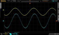
Still had crossover distortion at 4R load but with no load it vanished! What does this indicate to you?
Output is the blue trace, yellow the input.
Oh, and the same results at 10Khz but no pics.
Mooly,
Sorry this took two days but yard work called!
No pic but there was a clean signal at the junction of D4 & 5.
3mv at the servo output.
Still had crossover distortion at 4R load but with no load it vanished! What does this indicate to you?
Output is the blue trace, yellow the input.
Oh, and the same results at 10Khz but no pics.
Attachments
Well it points to crossover distortion and no bias but it must be said even if that were so its pretty extreme to be so visible.
Lets throw a wild card out there... scope the rails with the amp under load and producing the distortion. Use AC coupling for the scope. The rails on the board should be clean (and be careful measuring... don't blow it up") )
)
Have you used any sort of chokes in the DC supplies to the PCB, particularly anything shared between the pos and neg rail like chokes on a common former.
Also have you used any kind of ferrite component in the output feed. The output inductor must be air spaced and not wound on a magnetic former.
Also no ferrite beads slipped over any leads?
Lets throw a wild card out there... scope the rails with the amp under load and producing the distortion. Use AC coupling for the scope. The rails on the board should be clean (and be careful measuring... don't blow it up
)Have you used any sort of chokes in the DC supplies to the PCB, particularly anything shared between the pos and neg rail like chokes on a common former.
Also have you used any kind of ferrite component in the output feed. The output inductor must be air spaced and not wound on a magnetic former.
Also no ferrite beads slipped over any leads?
Lets throw a wild card out there... scope the rails with the amp under load and producing the distortion. Use AC coupling for the scope. The rails on the board should be clean (and be careful measuring... don't blow it up )
I'm assuming you want the rails scoped at the power inlet of the SGC board?
No chokes or ferrite used anywhere and the inductors were formed on a wooden dowel.
Speaking of inductance...the load resistors I use MAY have some inductance. The ones I use are the same ones P. Millet used in his dummy load project on this page;
Audio Dummy Load and were purchased from here;
Non-Inductive Resistors - 0 Ohm to 700 Ohm
That said, I should point out that I've used these load resistors while testing other amps that showed no crossover distortion but I still consider myself a novice when it comes to using an oscilloscope!
Lets throw a wild card out there... scope the rails with the amp under load and producing the distortion. Use AC coupling for the scope. The rails on the board should be clean (and be careful measuring... don't blow it up )
I'm assuming you want the rails scoped at the power inlet of the SGC board?
No chokes or ferrite used anywhere and the inductors were formed on a wooden dowel.
Speaking of inductance...the load resistors I use MAY have some inductance. The ones I use are the same ones P. Millet used in his dummy load project on this page;
Audio Dummy Load and were purchased from here;
Non-Inductive Resistors - 0 Ohm to 700 Ohm
That said, I should point out that I've used these load resistors while testing other amps that showed no crossover distortion but I still consider myself a novice when it comes to using an oscilloscope!
I had similar crossover distortion with LM4780, probably it might be defective chip, tried some capacitor compensation to see if some kind of oscillation is happening. But nothing helped, since it is hard to replace this chip I tossed it out.
lm4780 crossover distortion at higher output levels
Lets throw a wild card out there... scope the rails with the amp under load and producing the distortion. Use AC coupling for the scope. The rails on the board should be clean (and be careful measuring... don't blow it up )
I'm assuming you want the rails scoped at the power inlet of the SGC board?
No chokes or ferrite used anywhere and the inductors were formed on a wooden dowel.
Speaking of inductance...the load resistors I use MAY have some inductance. The ones I use are the same ones P. Millet used in his dummy load project on this page;
Audio Dummy Load and were purchased from here;
Non-Inductive Resistors - 0 Ohm to 700 Ohm
That said, I should point out that I've used these load resistors while testing other amps that showed no crossover distortion but I still consider myself a novice when it comes to using an oscilloscope!
Yes, look at the rails as they enter the board as its probably a bit risky trying to probe the chip itself.
Its also worth checking the grounds (by scope) and making sure they all have no significant signal on them.
No low value resistor will have anything like enough inductance to cause problems, it would have to be hundreds of times more than that.
If nothing shows then I would replace one of the LM3886's from one sourced elswhere.
The lm3886 draws between 50 and 85ma according to the data sheet and a large part of that will be bias current for the output stage.
One good test would be to measure the current draw and you could do that by adding something like a 0.1 ohm into either rail feeding the board and measuring the volt drop across it. Edit... as there will be decoupling on the board a 1 ohm would get a more accurate result.
You would have to subtract the current drawn by the appropriate 78/79 reg and circuitry from the result and the easy way to do that is to also add another resistor in series with the appropriate Zener feeding the reg on the rail you are measuring. That resistor can be much higher, anywhere from say 10 ohm to 47 ohm. Calculate the current draw and subtract it from the calculated value across the 0.1 ohm.
I realize this is a longshot since it presupposes two identical, simultaneous flaws ; one for Left and another for Right ....
Maybe the hand-wound output inductors did not expose enough bare copper (after scraping away the enamel coating) on both ends, to get two good solder joints and two good electrical connections.
I.e., perhaps a DC ohmmeter would tell you that the end-to-end resistance of (R20 parallel L1) is closer to 10 ohms than to 0.001 ohms ... ?
_
Attachments
^ It is very strange.
Mark... the last scope shot does show a loss of around 'half a divisions worth' of amplitude when going from no load to 4 ohm.
It might be worth looking at the signal before and after the coil and maybe also just trying the resistive load connected to the input side of the coil rather than the output side... so short out the 10 ohm in other words.
A resistive load should not cause any stability issues without the coil present.
I realize this is a longshot since it presupposes two identical, simultaneous flaws ; one for Left and another for Right ....
Maybe the hand-wound output inductors did not expose enough bare copper (after scraping away the enamel coating) on both ends, to get two good solder joints and two good electrical connections.
I.e., perhaps a DC ohmmeter would tell you that the end-to-end resistance of (R20 parallel L1) is closer to 10 ohms than to 0.001 ohms ... ?
_
Mark & Mooly,
Since this would be the easiest thing to check I will start that.
I'll also scope the signal at the input of the coils.
When I scope the PS rails, exactly where am I putting the ground clip and where am I putting the probe? I'm guessing the +/- Voltages. I hope I have enough hands to take pics of the rail results!
The current checks will take longer. Gotta dig through the stash to see if I still have any 1R resistors. The ones I have might be 5W wirewounds that I use to use when biasing output tubes in guitar amps.
And how do I check the grounds for significant signals?
- Home
- Amplifiers
- Chip Amps
- Bob Cordell's Super Gain Clone PCB (LM3886) and a stripped-down version: Compact3886