Thanks FF
have to look -actually nothing with 100pF in my box...just ceramic
chris
The ceramic are fine for deciding the value. For your level of detailed listening, the type may be noticed.
I am not in my lab right now but as I recall, my storage is also ceramic.
I've only seen ceramic NP0/C0G used in that location. Neurochrome used a TDK FG28C0Gxxx on one of their amps I have in that location and I've also used Murata C0G for similar use in op amp circuits. I don't know if silver mica would be suitable as I've used them on small pF applications as are said to be better.
This is only an observation as I'm only an amp builder.
This is only an observation as I'm only an amp builder.
...step by step...
Hi again
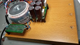
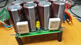
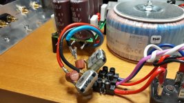
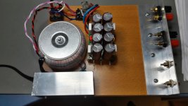
i did some work in the evening... the 2x 0,1µF are filter caps by wima. fuse is a 2,5A T - slow... --> interesting is that at the trani there is recommended to use 2 x 4A T=slow fuses (pic 2)
i test first the trani + rectifier - 20,2VAC
then i tested with cap bank - everything is fine.") 27,06V each rail without load...- - next step are the amp boards and the cabeling...
27,06V each rail without load...- - next step are the amp boards and the cabeling...
enough for this evening...yes is should clean my bench
chris
Hi again
i did some work in the evening... the 2x 0,1µF are filter caps by wima. fuse is a 2,5A T - slow... --> interesting is that at the trani there is recommended to use 2 x 4A T=slow fuses (pic 2)
i test first the trani + rectifier - 20,2VAC
then i tested with cap bank - everything is fine.
27,06V each rail without load...- - next step are the amp boards and the cabeling...enough for this evening...yes is should clean my bench
chris
Attachments
Last edited:
This thread has inspired me to (finally) replace my legacy 30 years old Marantz amplifier.
However i will take a different route as far as the power supply is concerned.
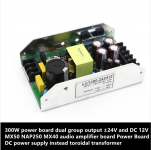
I bought a dedicated low noise Audio Powersuply (picture attached) for about 23 EUR from AliExpress.
This supply delivers +24V, -24V (about 6A) as well as 12V (1A) for auxillary devices. (adjustable within 10%)
Bit overkill maybe - but it should be able to get about 30W of clean power out of the LM1875t.
Supply is relatively compact and i expect building a decent amplifier with this supply should simplify matters considerably.
Output voltage of course is well regulated and remaining ripple less than typical 0.1V.
Hopefully will receive the PS in about two weeks, and first will try an unmodified LM1875t Ebay kit and do some measurements on PS and amplifier before building final system with original LM1875t and audio quality capacitors.
Will keep you informed ..
However i will take a different route as far as the power supply is concerned.
I bought a dedicated low noise Audio Powersuply (picture attached) for about 23 EUR from AliExpress.
This supply delivers +24V, -24V (about 6A) as well as 12V (1A) for auxillary devices. (adjustable within 10%)
Bit overkill maybe - but it should be able to get about 30W of clean power out of the LM1875t.
Supply is relatively compact and i expect building a decent amplifier with this supply should simplify matters considerably.
Output voltage of course is well regulated and remaining ripple less than typical 0.1V.
Hopefully will receive the PS in about two weeks, and first will try an unmodified LM1875t Ebay kit and do some measurements on PS and amplifier before building final system with original LM1875t and audio quality capacitors.
Will keep you informed ..
Attachments
Last edited:
This thread has inspired me to (finally) replace my legacy 30 years old Marantz amplifier.
However i will take a different route as far as the power supply is concerned.
I bought a dedicated low noise Audio Powersuply (picture attached) for about 23 EUR from AliExpress.
This supply delivers +24V, -24V (about 6A) as well as 12V (1A) for auxillary devices. (adjustable within 10%)
Bit overkill maybe - but it should be able to get about 30W of clean power out of the LM1875t.
Supply is relatively compact and i expect building a decent amplifier with this supply should simplify matters considerably.
Output voltage of course is well regulated and remaining ripple less than typical 0.1V.
Hopefully will receive the PS in about two weeks, and first will try an unmodified LM1875t Ebay kit and do some measurements on PS and amplifier before building final system with original LM1875t and audio quality capacitors.
Will keep you informed ..
Though I only found it at a somewhat higher price, I am looking forward to hear your opinion about this supply.
Hi FF,
Yes, i took advantage of the Sale action on 11.11 (Chinese single day) and paid $19.20 plus shipping. Now i see it is $24.
Probably coming Black Friday (29-11) is another good buying opportunity.
I took it from here: LCT300 2x24V@6A
Yes, i took advantage of the Sale action on 11.11 (Chinese single day) and paid $19.20 plus shipping. Now i see it is $24.
Probably coming Black Friday (29-11) is another good buying opportunity.
I took it from here: LCT300 2x24V@6A
Last edited:
Hi FF,
Yes, i took advantage of the Sale action on 11.11 (Chinese single day) and paid $19.20 plus shipping. Now i see it is $24.
Probably coming Black Friday (29-11) is another good buying opportunity.
I took it from here: LCT300 2x24V@6A
Many thanks, today 30.71 Eur (total). I will watch out for 29/11.
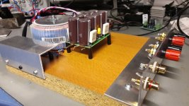
amp 2 mock up ready and its powered up...
Good evening
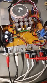
the mock up amp 2 is finished and is running since 2,5 hours with a sweep of 70mVrms into 8R. = about 0,6W
DC offset is -1,4mV and Rchannel has -1,9mV , psu shows in idle about 26,29V each rail.
lets run this amp some hours before i psuh my speakers - KEF Q100.
chris
Good evening
the mock up amp 2 is finished and is running since 2,5 hours with a sweep of 70mVrms into 8R. = about 0,6W
DC offset is -1,4mV and Rchannel has -1,9mV , psu shows in idle about 26,29V each rail.
lets run this amp some hours before i psuh my speakers - KEF Q100.
chris
Attachments
...R2 shorted....
Hi
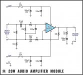
i read something and i am not sure if i mix something.pic 1 shows the schematic of the kit. as decribed at post 273
https://www.diyaudio.com/forums/chip-amps/341675-ebay-mono-lm1875-kit-28.html#post5963149
i shorted the R2, this is the 10R directly at the input to GND, near the 1MR at the negative input.
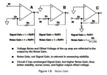
i found a drawing and i want be clear if the circuit C is the resistor R3 which should be added -maybe on both inputs of the LM1875?
chris
Hi
i read something and i am not sure if i mix something.pic 1 shows the schematic of the kit. as decribed at post 273
https://www.diyaudio.com/forums/chip-amps/341675-ebay-mono-lm1875-kit-28.html#post5963149
i shorted the R2, this is the 10R directly at the input to GND, near the 1MR at the negative input.
i found a drawing and i want be clear if the circuit C is the resistor R3 which should be added -maybe on both inputs of the LM1875?
chris
Attachments
Hi Chris,
My impression is that the two sketches are concerned with different matters:
The first sketch shows how you have a signal ground and a power ground only connected through 10 Ohm, thus a way to reduce coupling of noise from the power ground to signal ground.
The second sketch (version C) is dealing with a different aim outlined in particular in the second and third bullets. With a resistor connected between the inverting and non-inverting inputs, you can increase the "noise-gain" while you at the same time maintain the signal gain and with the advantage that you increase loop stability. A trick I believe to have seen for a non-inverting coupling such that the signal gain can be reduced below the minimum gain specified (for LM1875 20dB) while the amplifier remains stable. The downsides are offset and noise (can't win them all).
ringing at higher power
Hi again
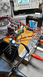
After about 30 hours run in with small power = 70mVrms
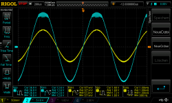
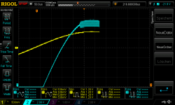
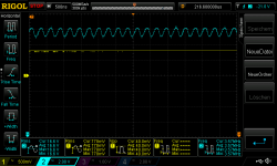
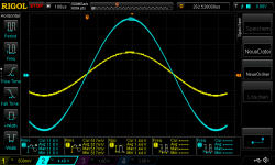
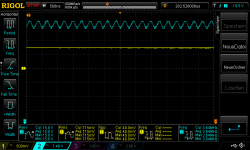
with my latest mock up i want to do a power test and found a "ringing" at the top of a 1khz sinwave +V. i start with max 600mVrms input into 8R so it should be nearly 20W per channel. i get here a havey distortion on the top as you can see. i didi this with 550mVrm input , 500mvrms input-you see the detailed scoping thats about 3,7 Mhz. at the 450mvrms its gone-or lets say not visible.
pic 1 600mVRms 1khz into 8R Rchannel
pic 2 550mVRms 1khz into 8R Rchannel
pic 3 550mVRms 1khz into 8R Rchannel_detailed
pic 4 500mVRms 1khz into 8R Rchannel
pic 5 500mVRms 1khz into 8R Rchannel_detailed
any ideas? the only thing i guess is that this are these "recovered" LM1875 chips
at 450mVrms the psu voltage go done just to 24V per rail - its good/strong
chris
Hi again
After about 30 hours run in with small power = 70mVrms
with my latest mock up i want to do a power test and found a "ringing" at the top of a 1khz sinwave +V. i start with max 600mVrms input into 8R so it should be nearly 20W per channel. i get here a havey distortion on the top as you can see. i didi this with 550mVrm input , 500mvrms input-you see the detailed scoping thats about 3,7 Mhz. at the 450mvrms its gone-or lets say not visible.
pic 1 600mVRms 1khz into 8R Rchannel
pic 2 550mVRms 1khz into 8R Rchannel
pic 3 550mVRms 1khz into 8R Rchannel_detailed
pic 4 500mVRms 1khz into 8R Rchannel
pic 5 500mVRms 1khz into 8R Rchannel_detailed
any ideas? the only thing i guess is that this are these "recovered" LM1875 chips
at 450mVrms the psu voltage go done just to 24V per rail - its good/strong
chris
Attachments
-
 600mvrms input 1khz into 8R Rchannel.png51 KB · Views: 181
 -
 550mvrms input 1khz into 8R Rchannel.png41.1 KB · Views: 53
 -
 550mvrms input 1khz into 8R Rchannel_2.png40.3 KB · Views: 42
 -
 500mvrms input 1khz into 8R Rchannel.png44.9 KB · Views: 57
 -
 500mvrms input 1khz into 8R Rchannel_2.png41.6 KB · Views: 45
Last edited:
- Status
- This old topic is closed. If you want to reopen this topic, contact a moderator using the "Report Post" button.
- Home
- Amplifiers
- Chip Amps
- eBay mono LM1875 kit