These kits are nobrainer for $1.4 on Ali and it will be cheaper on 29.11. something like $1.2 Even without changing parts you get nice sound.
Hi again
After about 30 hours run in with small power = 70mVrms
with my latest mock up i want to do a power test and found a "ringing" at the top of a 1khz sinwave +V. i start with max 600mVrms input into 8R so it should be nearly 20W per channel. i get here a havey distortion on the top as you can see. i didi this with 550mVrm input , 500mvrms input-you see the detailed scoping thats about 3,7 Mhz. at the 450mvrms its gone-or lets say not visible.
pic 1 600mVRms 1khz into 8R Rchannel
pic 2 550mVRms 1khz into 8R Rchannel
pic 3 550mVRms 1khz into 8R Rchannel_detailed
pic 4 500mVRms 1khz into 8R Rchannel
pic 5 500mVRms 1khz into 8R Rchannel_detailed
any ideas? the only thing i guess is that this are these "recovered" LM1875 chips
at 450mVrms the psu voltage go done just to 24V per rail - its good/strong
chris
This is the type of self-oscillation "collapse" I observed as well.
Less tendency of oscillation with lower supply voltage and higher value load resistors.
Is this with a possibly "fake" or a genuine LM1875?
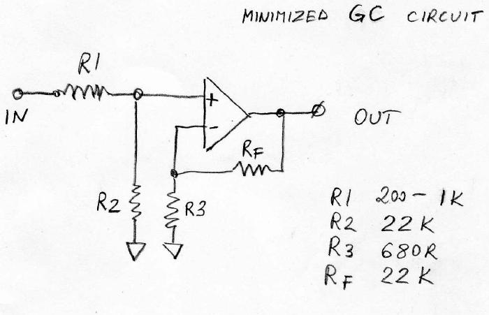
Has anyone built a LM1875 as a minimized Gainclone with only 4 resistors (2 on input and 2 on feedback) like Peter Daniel's LM3875 or Chipamp.com. I have one of PD/Chipamp here and got me thinking as it works well.
This is the type of self-oscillation "collapse" I observed as well.
Less tendency of oscillation with lower supply voltage and higher value load resistors.
Is this with a possibly "fake" or a genuine LM1875?
hi FF
yes these are the amazon - recovered chips -i did the shorted test and they survived. nevertheless i want to hear on my speakers in lower level to compare the different amp configurations.
chris
Has anyone built a LM1875 as a minimized Gainclone with only 4 resistors (2 on input and 2 on feedback) like Peter Daniel's LM3875 or Chipamp.com. I have one of PD/Chipamp here and got me thinking as it works well.
Hi rabbitz
do you mean to omit the FB cap? like written here? post 24
https://www.diyaudio.com/forums/chip-amps/344300-lm1875-amp-review-request-3.html#post5985207
chris
I mean getting rid of everything except the input and feedback resistors like this.
Commercial Gainclone kit- building instructions
Commercial Gainclone kit- building instructions
These kits are nobrainer for $1.4 on Ali and it will be cheaper on 29.11. something like $1.2 Even without changing parts you get nice sound.
Actually NO you won't ! it's basically shite.
IF using ALL genuine parts on that PCB you will get a Pretty good sound.
But certainly not as good as a current design decent quality amp .
Hobby dicking about is a clear entertainment source..understood... but let's not perpetuate Fantasy.
Actually NO you won't ! it's basically shite.
IF using ALL genuine parts on that PCB you will get a Pretty good sound.
But certainly not as good as a current design decent quality amp .
Hobby dicking about is a clear entertainment source..understood... but let's not perpetuate Fantasy.
hi bare
you wrote
But certainly not as good as a current design decent quality amp .
which one is your favortie?
chris
But certainly not as good as a current design decent quality amp .
Chipamps (LM3886, LM3875, LM4780) can perform very well as long as they are used within their limits. I find my recent ones are as enjoyable as some of the other solid state amps I've built such as AKSA 55N+, LF55, BAKSA, NX150, NXV200, P3A, P101 etc. Sure, they don't have the grunt or flexibility of those but my needs are simple these days.
These days I don't want to bugger around with more complex and larger circuits that require bias adjustments etc. Too old and lack the motor skills and eyesight for that now.
Last edited:
Actually NO you won't ! it's basically shite.
IF using ALL genuine parts on that PCB you will get a Pretty good sound.
But certainly not as good as a current design decent quality amp .
Hobby dicking about is a clear entertainment source..understood... but let's not perpetuate Fantasy.
For $1.2 YES you will.
Hello again
SQ compare - amp1_2 is the amp with the gren UES caps, amp1 is the amp with the hugh psu cap bank...but more detailed😛
both amp have 27db gain (should have 23 according to the original setting) but i guess the values aof the resistors are both in the widest corner to have finaly 27db.R2 is shorted and the 100pF ceramic is parallel to the 22k Fb resistor. both get the 120VA 18-0-18 trani and the same rectifier.
what is different?
amp2 has the recovered lm1875 and the 4,7µF wima as input cap+ a 22µF ues green nichicon feedback cap. 1000µF/50 supply caps per rail at the pcb + bigger psu cap bank
about 15000µF per rail measured
amp1_2 has the 10µF + 100µF ues green nichicon, 2x 100µF original caps per rail at the pcp + the bit smaller psu cap bank about 11000µF measured
first the lm1875 recoverd are playing fine - we see the ringing at the last posts but at my listening level i get luckly nothing up to now soundwise.
after 4 times listening sessions the last week i have to say that both play very similar - the difference is: the amp2 with the bigger cap bank is really more quiet and give a better feeling of "be quiet" - amp1_2 has a better character with "swing out " of the vocals and instruments.
chris
Last edited:
Chris, to stabilize your recovered LM1875 that tends to have self-oscillation at the top, you could try the trick from your posting #316, 2nd sketch, number (c). A resistor between the two inputs of the LM1875 may increase the loop stability. Start with 1K and work your way downwards.
Chris, to stabilize your recovered LM1875 that tends to have self-oscillation at the top, you could try the trick from your posting #316, 2nd sketch, number (c). A resistor between the two inputs of the LM1875 may increase the loop stability. Start with 1K and work your way downwards.
Hi FF
your are quick !🙂 ..thanks i will try this. to be honest for a final amp i will change the chip to a genuine chip which i bought.
chris
Hi FF
you know the LM1875 very well. what do you think about rabbitz´s idea refered to peter daniels method?
Has anyone built a LM1875 as a minimized Gainclone with only 4 resistors (2 on input and 2 on feedback) like Peter Daniel's LM3875 or Chipamp.com. I have one of PD/Chipamp here and got me thinking as it works well.
post 323
https://www.diyaudio.com/forums/chip-amps/341675-ebay-mono-lm1875-kit-33.html#post5985415
post 326
https://www.diyaudio.com/forums/chip-amps/341675-ebay-mono-lm1875-kit-33.html#post5986042
i am think about that but with a "safety" input cap
chris
A genuine chip I find is a good idea. My suggestion serves for you (and us) to learn more about the tricks that are available when we end up in trouble, and that may only be with a "fake" chip.
Hi FF
you know the LM1875 very well. what do you think about rabbitz´s idea refered to peter daniels method?
Has anyone built a LM1875 as a minimized Gainclone with only 4 resistors (2 on input and 2 on feedback) like Peter Daniel's LM3875 or Chipamp.com. I have one of PD/Chipamp here and got me thinking as it works well.
post 323
https://www.diyaudio.com/forums/chip-amps/341675-ebay-mono-lm1875-kit-33.html#post5985415
post 326
https://www.diyaudio.com/forums/chip-amps/341675-ebay-mono-lm1875-kit-33.html#post5986042
i am think about that but with a "safety" input cap
chris
As I recall my LM1875 days, I tried the 4 resistor DC coupled version with two probably "fake" LM1875 and it worked. In principle you can leave out R2 going from the non-inverting input and to ground IF you do NOT have a DC-decoupling capacitor at the input.
The problem with the DC-coupled LM1875 is that you have the input offset of the LM1875 times the LM1875 gain at the LM1875 output. I used them with an OP-AMP in a composite amplifier coupling with feedback from the LM1875 output such that it was the OP-AMP input offset I ended up with at the LM1875 output.
A genuine chip I find is a good idea. My suggestion serves for you (and us) to learn more about the tricks that are available when we end up in trouble, and that may only be with a "fake" chip.
yes i understand you...thanks!

As I recall my LM1875 days, I tried the 4 resistor DC coupled version with two probably "fake" LM1875 and it worked. In principle you can leave out R2 going from the non-inverting input and to ground IF you do NOT have a DC-decoupling capacitor at the input.
The problem with the DC-coupled LM1875 is that you have the input offset of the LM1875 times the LM1875 gain at the LM1875 output. I used them with an OP-AMP in a composite amplifier coupling with feedback from the LM1875 output such that it was the OP-AMP input offset I ended up with at the LM1875 output.
yes i remember/ and note it😉
composite amplifiers
is the DC/compisite better soundwise? or what advantages?
chris
- Home
- Amplifiers
- Chip Amps
- eBay mono LM1875 kit