Did all the swapping R to L etc all the way through. Not a problem as it's pulled apart and have moved on.
🙁...sorry
ask ESP directly?
chris
Not worth the effort as it was never going to be used as I have too many not being used. I've built over 30 SS amps and this is the only one that beat me.
Not worth the effort as it was never going to be used as I have too many not being used. I've built over 30 SS amps and this is the only one that beat me.
30 : 1 is a very good quote !!😉😀
Last edited:
...measurments with caps at the speakers terminal
Hi
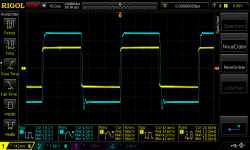
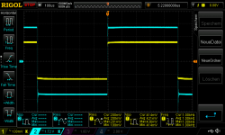
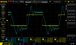
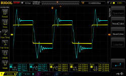
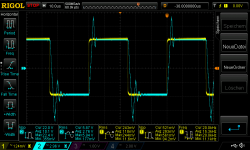
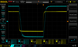
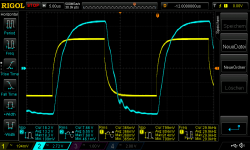
i was motivated to try a square wave test at my listening "mock up amp".
i use a 220nF at one channel to look at . the cap is a grey Kemet 220nF MKP X2 / 275VAC load is 8R non inductive on both channel.
its about 10,8 Watt each channel
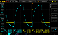
pic 1 200mVrms in square 10khz_220nF
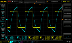
pic 2 200mVrms in square 20khz_220nF
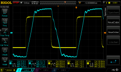
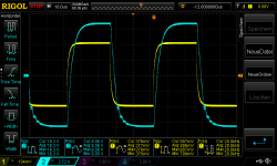
pic 3 400mVrms in square 10khz_220nF
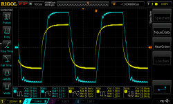
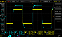
pic 4 400mVrms in square 20khz_220nF
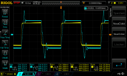
oscillating..
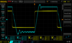
pic 5 700mVrms in square 10khz_220nF
pic 6 700mVrms in square 20khz_220nF
after this bad oscillating i will not do 4R test with max power...
some comments or ideas?
chris
Hi
i was motivated to try a square wave test at my listening "mock up amp".
i use a 220nF at one channel to look at . the cap is a grey Kemet 220nF MKP X2 / 275VAC load is 8R non inductive on both channel.
its about 10,8 Watt each channel
pic 1 200mVrms in square 10khz_220nF
pic 2 200mVrms in square 20khz_220nF
pic 3 400mVrms in square 10khz_220nF
pic 4 400mVrms in square 20khz_220nF
oscillating..
pic 5 700mVrms in square 10khz_220nF
pic 6 700mVrms in square 20khz_220nF
after this bad oscillating i will not do 4R test with max power...
some comments or ideas?
chris
Attachments
-
 200mVrms in square 10khz_220nF.png43.6 KB · Views: 260
 -
 200mVrms in square 20khz_220nF.png46.9 KB · Views: 265
 -
 400mVrms in square 10khz_220nF.png45.4 KB · Views: 266
 -
 400mVrms in square 20khz_220nF.png49.6 KB · Views: 278
 -
 700mVrms in square 10khz_220nF_ringing.png45 KB · Views: 272
 -
 700mVrms in square 20khz_220nF_ringing.png47 KB · Views: 87
Last edited:
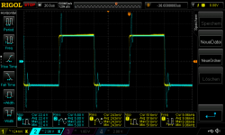
its gooing worse with 440nF
here is the same test but i try the other channel - L channel but with 440nF...same cap type.
now with just 200mVrms at 8R its about 2,6Watt per channel
pic1 200mVrms in square 1khz_440nF_L channel
pic2 200mVrms in square 1khz_440nF_L channel_2
pic3 200mVrms in square 10khz_440nF_L channel
pic4 200mVrms in square 20khz_440nF_L channel
pic5 200mVrms in square 30khz_440nF_L channel
Attachments
-
 200mVrms in square 30khz_440nF_L channel.png54.3 KB · Views: 84
 -
 200mVrms in square 20khz_440nF_L channel.png49.4 KB · Views: 80
 -
 200mVrms in square 10khz_440nF_L channel.png45.4 KB · Views: 78
 -
 200mVrms in square 1khz_440nF_L channel_2.png43.4 KB · Views: 88
 -
 200mVrms in square 1khz_440nF_L channel.png42.9 KB · Views: 89
...bad at 440nF and 400mVrms input
pic1 400mVrms in square 1khz_440nF_L channel
pic2 400mVrms in square 1khz_440nF_L channel_2
pic3 400mVrms in square 10khz_440nF_L channel
pic4 400mVrms in square 20khz_440nF_L channel
pic5 400mVrms in square 30khz_440nF_L channel
its about 10,5 Watt at 8R
pic1 400mVrms in square 1khz_440nF_L channel
pic2 400mVrms in square 1khz_440nF_L channel_2
pic3 400mVrms in square 10khz_440nF_L channel
pic4 400mVrms in square 20khz_440nF_L channel
pic5 400mVrms in square 30khz_440nF_L channel
its about 10,5 Watt at 8R
Attachments
-
 400mVrms in square 30khz_440nF_L channel.png47.1 KB · Views: 78
 -
 400mVrms in square 20khz_440nF_L channel.png51.2 KB · Views: 71
 -
 400mVrms in square 10khz_440nF_L channel.png49.2 KB · Views: 66
 -
 400mVrms in square 1khz_440nF_L channel_2.png40.5 KB · Views: 69
 -
 400mVrms in square 1khz_440nF_L channel.png42.6 KB · Views: 77
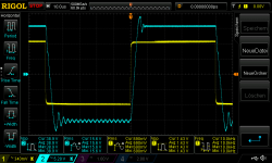
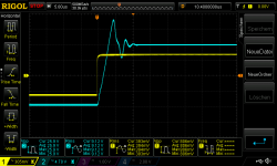
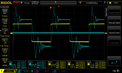
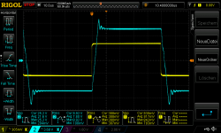
As i wrote i listening since weeks and i found to use a "zobel 220nF +10R" at the speakers output as better sound.
the only way i can explain "technically" is a comparison. no zobel is the swing bigger = overshoot and it is a longer swing
pic1 400mVrms in square 10khz_440nF_L channel
pic2 400mVrms in square 10khz_440nF_L channel - no zobel
pic3 400mVrms in square 20khz_440nF_L channel
pic4 400mVrms in square 20khz_440nF_L channel - no zobel
pic5 400mVrms in square 30khz_440nF_L channel
pic6 400mVrms in square 30khz_440nF_L channel - no zobel
chris
Attachments
-
 400mVrms in square 30khz_440nF_L channel_no zobel.png62 KB · Views: 79
 -
 400mVrms in square 30khz_440nF_L channel.png47.1 KB · Views: 68
 -
 400mVrms in square 20khz_440nF_L channel_no zobel.png53.9 KB · Views: 68
 -
 400mVrms in square 20khz_440nF_L channel.png51.2 KB · Views: 79
 -
 400mVrms in square 10khz_440nF_L channel_no zobel.png50.2 KB · Views: 69
 -
 400mVrms in square 10khz_440nF_L channel.png49.2 KB · Views: 85
Thanks to John audio tech for that idea = test the stabilisation of an amp🙂
actually i am afraid to test with 4R load..😉
actually i am afraid to test with 4R load..😉
I ´d play around with max power test - i use a 100hZ tone.
here some compare data´s sinus vs square wave
no caps on the speakers just the zobel and the non inductive 8R.
sinus max input is 600mVrms = 40,4Vpp and 13,8Vrms at 8R its about 24Watt
the rails are in idle at my amp +/- 26,6V = 53,2V
during this max test i get a non sync. rail voltage drop with 23V and 23,3V = 46,3 i loose 6,9Volts.
square test is harder - but i was able to "climb" to the rail nearer...
max input is 900mVrms square = 42,5Vpp and 19,6Vrms at 8R its about 48Watt
the rails are in idle at my amp +/- 26,6V = 53,2V
during this max test i get a non sync. rail voltage drop with 21,7V and 22,1V = 43,8 i loose 9,4Volts.
chris
good night
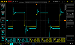
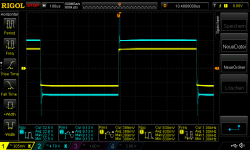
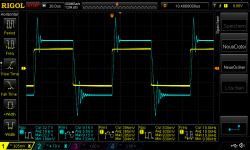
...avoi oscillation..method 1 . add 47pF at feedback
Hi
i am not sure if this is the best method but i solder a 47pF cap in parallel to the 22k Feedback resistor. any other hints are very welcome.
R channel input is 400mVrms into 8R and the 440nF cap on the speaker terminal.
pic 1 400mVrms in square 10khz_440nF_R channel
pic 2 400mVrms in square 10khz_440nF_R channel + 47pF feedback
pic 3 400mVrms in square 20khz_440nF_R channel
pic 4 400mVrms in square 20khz_440nF_R channel + 47pF feedback
pic 5 400mVrms in square 30khz_440nF_R channel
pic 6 400mVrms in square 30khz_440nF_R channel + 47pF feedback
any comments/ideas ?
chris
Attachments
-
 400mVrms in square 30khz_440nF_R channel_47pF feeback.png54.4 KB · Views: 84
 -
 400mVrms in square 30khz_440nF_L channel.png47.1 KB · Views: 78
 -
 400mVrms in square 20khz_440nF_R channel_47pF feedback.png51.3 KB · Views: 84
 -
 400mVrms in square 20khz_440nF_L channel.png51.2 KB · Views: 83
 -
 400mVrms in square 10khz_440nF_R channel_47pF feedback.png45.1 KB · Views: 77
 -
 400mVrms in square 10khz_440nF_L channel.png49.2 KB · Views: 78
recovered chips cannot do the same performance?
Hi
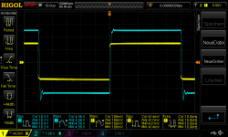
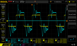
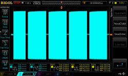
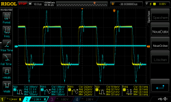
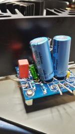
i want to try this square wave test on the other boards too. this boards are with the 1875 recovered - shortcut survived. the test is with my lab psu set to 27V, 3A each rail. 250mV is the maximum because after some seconds a kind of protection mode kicks in! every 2,5 seconds the chip is switching on/off.
pic 1 this is the board i tested.
pic 2 250mVrms square in 10kHz at 8R + 440nF cap
pic 3 250mVrms square in 20kHz at 8R + 440nF cap
pic 4 250mVrms square in 30kHz at 8R + 440nF cap
pic 5 show you with a long time set that every 2,5 seconds the chip is switching off -my psu shows me that the voltages drops to zero.
this phenomenon i get just at the other amp with max power and high frequency. so for me this chip actually are not 100% "recovered"
do somebody have the same experience??
chris
Hi
i want to try this square wave test on the other boards too. this boards are with the 1875 recovered - shortcut survived. the test is with my lab psu set to 27V, 3A each rail. 250mV is the maximum because after some seconds a kind of protection mode kicks in! every 2,5 seconds the chip is switching on/off.
pic 1 this is the board i tested.
pic 2 250mVrms square in 10kHz at 8R + 440nF cap
pic 3 250mVrms square in 20kHz at 8R + 440nF cap
pic 4 250mVrms square in 30kHz at 8R + 440nF cap
pic 5 show you with a long time set that every 2,5 seconds the chip is switching off -my psu shows me that the voltages drops to zero.
this phenomenon i get just at the other amp with max power and high frequency. so for me this chip actually are not 100% "recovered"
do somebody have the same experience??
chris
Attachments
-
 protection mode every 3 seconds.png44.1 KB · Views: 261
 -
 200mVrms square in 30kHz at 8R + 440nF cap.png57.3 KB · Views: 261
 -
 200mVrms square in 20kHz at 8R + 440nF cap.png48.7 KB · Views: 263
 -
 200mVrms square in 10kHz at 8R + 440nF cap.png48.2 KB · Views: 263
 -
 4µ7wima22µES_1000µFrail_1.jpg214.4 KB · Views: 273
Comment: Reducing bandwidth (47pF) seems to improve stability margin.
Idea: Try with 220pF instead of the 47pF.
Idea: Try with 220pF instead of the 47pF.
Comment: Reducing bandwidth (47pF) seems to improve stability margin.
Idea: Try with 220pF instead of the 47pF.
Hello FF
Thank you for your advice ! ...i will do so.
chris
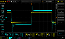
..220pf at the feedback
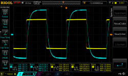
Hi
here is the result at my mock up amp. i did the test with 400mvrms into 8R and 440nF cap at the R channels output. L channel just 8R.
400mVrms in square 10khz_440nF_R channel_220pF feedback
400mVrms in square 20khz_440nF_R channel_220pF feedback
400mVrms in square 30khz_440nF_R channel_220pF feedback
chris
Attachments
Hi
here is the result at my mock up amp. i did the test with 400mvrms into 8R and 440nF cap at the R channels output. L channel just 8R.
400mVrms in square 10khz_440nF_R channel_220pF feedback
400mVrms in square 20khz_440nF_R channel_220pF feedback
400mVrms in square 30khz_440nF_R channel_220pF feedback
chris
Many thanks.
Too slow, 100pF should be right. Eventually, try to hear if you notice the difference between no capacitor and 100pF with music.
Hi FF
Actually i listening with 220pf at the feedback about 2.5 hours and compare to my TPA3255.
the lm 1875 is now a different - better amp😎 - its clear and deeper sound stage, partly i go through some older album and its sounds very very nice.
nevertheless i will modify the cap to the 100pf to get faster response...
thanks
chris
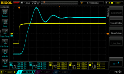
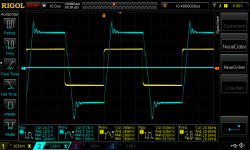
...100pf in the feedback
Good morning
here is the test with my mock up amp (amp 1_2) with the feedback cap of 100pf each channel. test is with 8R and the Rchannel is the 440nF cap load added.
pic 1 400mVrms in square 10khz_440nF_R channel 100pF feedback
pic 2 400mVrms in square 20khz_440nF_R channel 100pF feedback
pic 3 400mVrms in square 30khz_440nF_R channel 100pF feedback
i tried 600mVvrms in ..it is stable
pic 4 600mVrms in square 10khz_440nF_R channel 100pF feedback
pic 5 600mVrms in square 20khz_440nF_R channel 100pF feedback
pic 6 600mVrms in square 10khz_440nF_R channel 100pF feedback
listening not done...(kefQ100)
as i wrote the post before - the sound - with 220pf - was very dynamic and clear without "noise/fog " in the background. the details get much better without harshness or bad high snake t,z,s..
chris
Attachments
-
 600mVrms in square 30khz_440nF_R channel 100pF feedback.png50.4 KB · Views: 82
 -
 600mVrms in square 20khz_440nF_R channel 100pF feedback.png52.3 KB · Views: 91
 -
 600mVrms in square 10khz_440nF_R channel 100pF feedback.png43.9 KB · Views: 78
 -
 400mVrms in square 30khz_440nF_R channel 100pF feedback.png48.1 KB · Views: 78
 -
 400mVrms in square 20khz_440nF_R channel 100pF feedback.png49 KB · Views: 95
 -
 400mVrms in square 10khz_440nF_R channel 100pF feedback.png48.3 KB · Views: 81
Hi
just a question : i use a ceramic style cap for this feedback - now 110pF. Should i use a polyprepylen cap (wima..) because of the bad vibration effect at the ceramic?
chris
just a question : i use a ceramic style cap for this feedback - now 110pF. Should i use a polyprepylen cap (wima..) because of the bad vibration effect at the ceramic?
chris
frequence response with 8R and 4R resistive load
Good morning
after all this changes i did a frequency response with resistive load 8R and 4R. input is 10mmVrms and that´s about 0,7W @8R and 1,3W @ 4R.
its a soft roll off of the gain of 27db nearly the same for 8R or 4R
17khz -0,3dB
23khz -0,5dB
31khz -1dB
47khz -2db
59khz -3db
chris
Good morning
after all this changes i did a frequency response with resistive load 8R and 4R. input is 10mmVrms and that´s about 0,7W @8R and 1,3W @ 4R.
its a soft roll off of the gain of 27db nearly the same for 8R or 4R
17khz -0,3dB
23khz -0,5dB
31khz -1dB
47khz -2db
59khz -3db
chris
Attachments
- Home
- Amplifiers
- Chip Amps
- eBay mono LM1875 kit