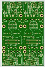
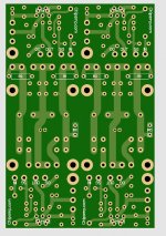
Here is another little different LM1875 TDA2030 board,
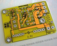
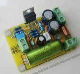
Any thoughts on this one?
Different LM1875 TDA2030 PCB with inductor


Any thoughts on this one?
Different LM1875 TDA2030 PCB with inductor
Last edited:
Any thoughts on how the Ebay layout/board compares to the Chipamp LM1875 layout/board?
View attachment 894328
View attachment 894329
Hi Dave
For me the pcb looks well done like the our pcb. its similar to sadface pcb to use a big film cap as input cap. i personal find that the decoupling caps 110nF or 220nF + electrolytic should be placed as near as possible at the chip. so ideally they should be soldered at the bottom side of the pcb directly at the pins.
the ebay board is well done..
chris
Here is another little different LM1875 TDA2030 board,
View attachment 894369
View attachment 894368
Any thoughts on this one?
Different LM1875 TDA2030 PCB with inductor
big space to use a fat film cap as input cap....fine.
0,7µH as output filter coil like the LM3886 boards is new for me.
Hi Dave
i noted this board. its from "Zero Zone" and looks not bad. the components are unknown. 1 pcb for a complete amplifier with enough space between the chips to have sufficient heat sink usage. i find this important if i want to use both amps at 1 pcb.
SUQIYA 20W Gaincard version of the two channel LM1875 power amplifier kit finished board tube flavor|Amplifier| - AliExpress
bare board - supply is AC-0-AC
DIY PCB for GC Gaincard Version Dual Channel LM1875 Power Amplifier PCB Empty Board Guts Power Amplifier Board|Amplifier| - AliExpress
chris
Last edited:
Here is another little different LM1875 TDA2030 board,
View attachment 894369
View attachment 894368
Any thoughts on this one?
Different LM1875 TDA2030 PCB with inductor
I'm no amp designer but I can see a few issues on this LM1875 PCB.
There's no 100nF by-pass caps near the chip and the Thiele network is incomplete. It has the 0.7uH inductor but no parallel resistor so it would not work as required. Better to link it out than have a non functioning filter. Maybe those items are under the PCB. I don't get the 47pF and 10K resistor.
IMO, the LM1875 PCB that started this thread if hard to beat on price, layout and component values.
Any thoughts on how the Ebay layout/board compares to the Chipamp LM1875 layout/board?
View attachment 894328
View attachment 894329
That's not the original Chipamp.com LM1875 PCB as they were mono boards and the power supply was very different. Looks like someone is using their name as Chipamp.com no longer exists AFAIK.
Hi guys,
I figured I'd leave this here in case anybody is interested.
I've designed an LM1875 PCB. I call it the Bigcap.
It turned out halfway between the old schoolies amp and the datasheet implementation.
-I removed the 10R ground lift resistor. It doesn't feature on the datasheet and my understanding is that this is generally unnecessary.
-I added fuse rails back onto the board that were taken off the Ebay pcb when they ripped off the schoolies PCB design.
-I've changed the screw terminals for power connections and outputs to spade connections.
- Space has been allocated around the 22uF feedback cap to allow large sized film caps (up to 27mm pitch) instead of an electrolytic can.
- Space has been allocated between the power supply decoupling caps to allow a screw driver to access the IC.
View attachment 807347
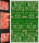
My board beside the ebay board
View attachment 807348
Populated big cap pcb beside the ebay board.
View attachment 807343
View attachment 807344
View attachment 807345
Attached are the gerber files if anybody feels like a JLCpcb order.
Given that the minimum order is 5 and these are typically used in pairs, I do have 1 spare board I could send for testing if somebody with test equipment is interested.
I could also provide something like a mouser BOM as thats where most of my parts have come from.
And how do you think this compares to the Ebay LM1875?
Fortunately I ordered 6 of the $2.00 Ebay LM1875 kits, because I had the same solder pad "disappear" on two of the boards when soldering and had to toss them.
I would like to order some quality LM1875 boards from PCBway or JLCPCB based on a known good design.
What was your BOM for this board?
Thank you,
David.
Hi David
i ordered from Sadface some boards but the delivery is not really fast .
.
in a technical view I would say that this board give you the advantage to use a big space of the input cap - film cap as feedback cap 22µF is huge! and fuses on board...and for sure a better quality for soldering.
chris
i ordered from Sadface some boards but the delivery is not really fast
in a technical view I would say that this board give you the advantage to use a big space of the input cap - film cap as feedback cap 22µF is huge! and fuses on board...and for sure a better quality for soldering.
chris
Last edited:
Hi
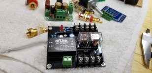
if you use a original chip LM1875 then its not needed. the short circuit protection is working fine. the dc protection board should have an additionally circuit for pop on/off - so if you feel better and you have enough space in your housing then you can use it.
i personally dont try a DC protection board. be aware of the Chinese "interpretation" --> test it before you use it.
chris
Hi
if you use a original chip LM1875 then its not needed. the short circuit protection is working fine. the dc protection board should have an additionally circuit for pop on/off - so if you feel better and you have enough space in your housing then you can use it.
i personally dont try a DC protection board. be aware of the Chinese "interpretation" --> test it before you use it.
chris
How do you test them?
Hi Dave
i didn´t test such a board but as i remember there is a chip/or a circuit on the pcb which is "detection" of the DC voltage Level. i cant remember the chips name.
DC speaker protection for audio amplifier - YouTube
connect the board with a lab supply and test it with 12V-to power up the DC board. then build a 1-5V input signal at the speakers terminal.
here a video about 1 minute....or at 4min with a battery AAA
What Does DC Voltage Do To Your Speaker ? Speaker Protection Circuit - YouTube
chris
Hi, in my experience with the lm1875 ebay boards, they do make for a pretty loud on/off thump or pop. And this was using all legit parts from digikey or such. Then again the 1875 lacks a mute pin so that shouldn't be a surprise I guess.
Dc protection aside, I think the time delay those little protection boards provide is a must have.
You will probably need a separate power supply and/or transformer too, so plan for that lost space.
Dc protection aside, I think the time delay those little protection boards provide is a must have.
You will probably need a separate power supply and/or transformer too, so plan for that lost space.
- Home
- Amplifiers
- Chip Amps
- eBay mono LM1875 kit
