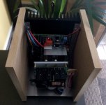
Here's a quick photo of the 3U 300mm deep case. The 2U case I think has adequate cooling but my caps won't fit so I went for 3U.
I was a bit disappointed with the feet. Poor quality.
Nice case.
You could also mount the PCB flat to the heat sink. I guess the height of the heat sinks are large enough. The added advantage is that you save space in the enclosure. You probably could use my drilling template if you wanted to go that way.
Nice case.
You could also mount the PCB flat to the heat sink. I guess the height of the heat sinks are large enough. The added advantage is that you save space in the enclosure. You probably could use my drilling template if you wanted to go that way.
Hey Delange. Thanks! I didn't really consider mounting the PCB parallel to the heatsink and I think even in 3U it's too tight. I have planned everything (I think) based on a low-level bracket perpendicular to the heatsink and I should be ok for space. My caps are 35mm diameter screwcaps and just fit 40mm apart (pre-drilled holes on 10mm grid) which is good.
Plan is to fit the caps on a 4x2 grid across the case with a gap up the centre for power. So, needs approx 180mm for caps, and the two PCBs take another 160mm = 340mm.
Similar layout to Jort by with DIY caps. No PCB there.
Popchops, case looks good.
How will you be doing the holes on the Heatsink?
Will you be replacing the original preset/trimmer for the better type?
Also if you're using SMPS's then you'll need to add the extra bits as described by 'delange'
Hi Calpe. No SMPS here... just oldskool screwcap caps joined by a copper ground plane. Would love to fit in a 10mH 5A inductor between the caps, but values would have to change for some and there is the risk of a voltage surge (above 60V) during the inductor settling time so I just don't have the confidence to do it. Shame though... simulations show the 100 Hz ripple reduced to 0.3V at full load, and nothing would survive at higher frequency. Effectively forces the final reservoir cap to charge continuously instead of in tiny 100 Hz zaps.
Too expensive and too big. I'm completely over it as you can see.
I'm going to print off and scale check the drilling template, mark the centres for 5 holes and use a mates drill to drill them. Will then test fit with standoffs and then drill the support holes. Then finally solder with supports in place.
I'm undecided about multi-turn trimmer. Costs about €13? I'm tempted to get the linear power supply up on an old (35 years...?) 35V 625VA tranny I've been gifted just to check my losses. Then I'll order 2x 37V probably or 37.5V maybe. With my scrap tranny I will check out the first channel and if it's as bad as people say then I'll fork out for the multiturn trimmer for the second channel.
The first Q-Watt channel I've build has been running for over a week in my main set. It is running on the right channel of my set. The left channel is driven by another power amplifier. The Q-Watt sounds very good and I'm happy with the SMPS. I can't hear any noticeable difference in sound quality between the two amps.
I still need to finish the enclosure. There's still a debate going on in my head about that...")
I will probably do something like in the attached picture although I'm not sure what material I will end up using (and what finish). I will probably close the enclosure with a piece of aluminium plate with square holes in it (don't know the correct name).
I still need to finish the enclosure. There's still a debate going on in my head about that...
I will probably do something like in the attached picture although I'm not sure what material I will end up using (and what finish). I will probably close the enclosure with a piece of aluminium plate with square holes in it (don't know the correct name).
Attachments
Final mounting stages underway at last!
Separate veroboard ready to mount the components for the mod given to us by 'delange'.
Transistors T1-T5 will be mounted, but their legs will not be soldered direct onto pcb, for me it's more practical and there's space anyway.
Once mounted wiring up will begin, fingers crossed.
Separate veroboard ready to mount the components for the mod given to us by 'delange'.
Transistors T1-T5 will be mounted, but their legs will not be soldered direct onto pcb, for me it's more practical and there's space anyway.
Once mounted wiring up will begin, fingers crossed.
Attachments
delange, silly question, but i'm assuming one SMPS mod is needed for each Q-Watt board?
Hi Calpe,
Yes, the preference is one mod for each power supply / amplifier combo. This way you keep a dual mono setup.
Your project is coming along nice I see.
Mine has been delayed because of a ski holiday... priorities
Final mounting stages underway at last!
Separate veroboard ready to mount the components for the mod given to us by 'delange'.
Transistors T1-T5 will be mounted, but their legs will not be soldered direct onto pcb, for me it's more practical and there's space anyway.
Once mounted wiring up will begin, fingers crossed.
I see you have been busy! I am just now going to test my soft start and begin assembling one half of the linear PS. SMPS would have ben quicker.....
Cheers delange & popchops. Will now fit the dual components for the SMPS mod and then begin on heatsink work then doing the wiring.
Not sure if i'll have enough fire extinguishers when i power up!
Don't worry, the Q-Watt amplifier is a nice amp. If you carefully populated the board and properly fitted the transistors there will be no fire
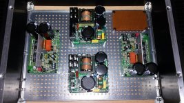
I put the enclosure together and finished the cabling in the amp. The enclosure is not finished yet though. I still need to build the rest of the enclosure. But I'm still toying with a few options for that in my mind.
If the bottom plate marks the dimensions of the amp, then your SMPS won't be happy in this position in the enclosure. The back will block more than half of the airflow of the heatsinks.
Hi Calpe. I think you have no fan right? So just convection cooling of the SMPS? It's a shame that it's not easier to mount the whole SMPS on your main heatsink.
Are you using 2x 500VA power supplies? So I guess for domestic use you won't normally use more than 10% of this.
Is there any way to make a thermal link from the SMPS to the steel base plate? From memory, the SMPS is 90% efficient right?
Are you using 2x 500VA power supplies? So I guess for domestic use you won't normally use more than 10% of this.
Is there any way to make a thermal link from the SMPS to the steel base plate? From memory, the SMPS is 90% efficient right?
Last edited:
If the bottom plate marks the dimensions of the amp, then your SMPS won't be happy in this position in the enclosure. The back will block more than half of the airflow of the heatsinks.
The bottomplate indeed markes the diamensions. However. The front and top of the final enclosure will be "open"; I'm going to use a perforated aluminium cover (square holes) to cover the front and top. This will allow more than enough airflow inside the enclosure.
I'll post some more pictures once the enclosure is finished.
Last edited:
I'm sure it's not needed for the low duty cycle with Q-Watt.
Would need to think again if using the SMPS at full rated output. Would need forced cooling.
I'm not worried; I have used my first channel for over a week in my system. During the whole period the Q-Watt amp and the power supply stayed very, very, very cool. Even at higher listening levels.
As you say, in domestic systems the amp will never run at high levels continously and as a result willl never develop high temperature. Regular airflow cooling is sufiecient; even in my "small" custom build enclosure.
- Home
- Amplifiers
- Chip Amps
- My Q-Watt project