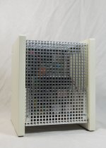
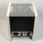
The bottomplate indeed markes the diamensions. However. The front and top of the final enclosure will be "open"; I'm going to use a perforated aluminium cover (square holes) to cover the front and top. This will allow more than enough airflow inside the enclosure.
I'll post some more pictures once the enclosure is finished.
That will not help you. The warmth 'wants' to rise. It cannot do that for the most of the heatsinks, a hotspot will occur. The parts will age very rapidly or even die of the heat. A defect SMPS can damage the whole amplifier, I would really suggest you change that problem. Mount the board horizontally, connect the heatsinks thermally with the case or use different heatsinks of 4x the size or heatsinks that have the fins pointing upwards.
It's good to hear your feedback delange.
The proof is in the pudding... the SMPS has thermal cutout right? So if it's not happy it would let you know.
The proof is in the pudding... the SMPS has thermal cutout right? So if it's not happy it would let you know.
Last edited:
That will not help you. The warmth 'wants' to rise. It cannot do that for the most of the heatsinks, a hotspot will occur. The parts will age very rapidly or even die of the heat. A defect SMPS can damage the whole amplifier, I would really suggest you change that problem. Mount the board horizontally, connect the heatsinks thermally with the case or use different heatsinks of 4x the size or heatsinks that have the fins pointing upwards.
You are right when we would be dealing with high temperature generating components. And when we would use this amp in a PA kind of setup where it would be running above 50% of its capacity continuously. In such cases I would mount the components differently. However in a home environment the amp stays cold and doesn't draw huge amount of currents. I'm using a 500 watts PS to make sure the amp has sufficient current when needed (peaks). So as a result, the PS stays cold as well. When I say cold, I mean I could touch the heat sinks and barely feel the warmth the components generated...
As mentioned before, during my tests (over a week) the amp and power supply didn't even break a sweat, not even when running the amp at higher listening levels. I mounted the PS this way to have a smaller footprint; which is important in my use case. So we need to put things in perspective...
the SMPS has thermal cutout right? So if it's not happy it would let you know.
Yes, the supply has thermal protection (amount others) built in should it reach unacceptable levels of heat.
You are right when we would be dealing with high temperature generating components. And when we would use this amp in a PA kind of setup where it would be running above 50% of its capacity continuously. In such cases I would mount the components differently. However in a home environment the amp stays cold and doesn't draw huge amount of currents. I'm using a 500 watts PS to make sure the amp has sufficient current when needed (peaks). So as a result, the PS stays cold as well. When I say cold, I mean I could touch the heat sinks and barely feel the warmth the components generated...
That's the case with ventilation at the moment and the power you're using right now. The ambient temperature can change, and the power needed too. Summer party maybe? A little yank at the bass knob which gives +6dB? And once it's found it's place the ventilation will probably be different. Why on earth would you build in a known potential point of failure?
As mentioned before, during my tests (over a week) the amp and power supply didn't even break a sweat, not even when running the amp at higher listening levels. I mounted the PS this way to have a smaller footprint; which is important in my use case. So we need to put things in perspective...
It fits also horizontally. Mount it on risers or with an additional 90° angle and that problem is gone.
Yes, the supply has thermal protection (amount others) built in should it reach unacceptable levels of heat.
No, that's not the case. The thermal protection triggers only when the IC reaches a too high temperature. There are no temperature sensor at the diodes, bridge rectifier, capacitors or resistors and most likely not on the transistors either. The capacitors will suffer greatly in life expectancy from the heat. Besides that, the U-shaped heatsinks are already cramped in very tightly. They are not meant to be used that closely and in that position.
Why mount a generous heatsink for the amp and totally ignore the PS? BTW: The PS isn't overdimensioned, the amp can consume over 560W.
Popchops idea of a fan sounds good, and prevention is always better, though it'd have to be an extraction one mounted on rear panel.
Having serviced electronics for many years, coolness is important and mounting e.g. electrolytics close to heatsinks is not a good idea as many manufacturers do.
Yes, one SMPS per Q-Watt amp, is the rule.
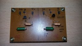
In my post 68, the Q-Watts are placed on the left and right side close to the heatsinks. I'm not wiring the transistor legs direct to the PCB's.
Looking forward to see other images posted, more to come from me soon.
Hopefully, if the SMPS develops a fault it would be hoped that it would not damage the Q-Watts.
http://www.connexelectronic.com/documents/SMPS500R.pdf
Happy building
Having serviced electronics for many years, coolness is important and mounting e.g. electrolytics close to heatsinks is not a good idea as many manufacturers do.
Yes, one SMPS per Q-Watt amp, is the rule.
In my post 68, the Q-Watts are placed on the left and right side close to the heatsinks. I'm not wiring the transistor legs direct to the PCB's.
Looking forward to see other images posted, more to come from me soon.
Hopefully, if the SMPS develops a fault it would be hoped that it would not damage the Q-Watts.
http://www.connexelectronic.com/documents/SMPS500R.pdf
Happy building
Last edited:
Popchops idea of a fan sounds good, and prevention is always better, though it'd have to be an extraction one mounted on rear panel.
Having serviced electronics for many years, coolness is important and mounting e.g. electrolytics close to heatsinks is not a good idea as many manufacturers do.
Yes, one SMPS per Q-Watt amp, is the rule.
In my post 68, the Q-Watts are placed on the left and right side close to the heatsinks. I'm not wiring the transistor legs direct to the PCB's.
Looking forward to see other images posted, more to come from me soon.
Hopefully, if the SMPS develops a fault it would be hoped that it would not damage the Q-Watts.
http://www.connexelectronic.com/documents/SMPS500R.pdf
Happy building
Calpe, don't be afraid of excessive heat. Your setup has plenty of natural cooling available. Some people are chasing ghosts...
And I would avoid using a fan since that make too much noise for domestic listening environments.
speaker relay switch off
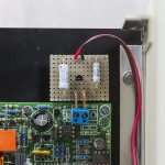
A small update in my project for the speaker relay switch off if using a SMPS.
Transistors to be mounted in the next day or so and wiring will begin.
A small update in my project for the speaker relay switch off if using a SMPS.
Transistors to be mounted in the next day or so and wiring will begin.
Attachments
Last edited:
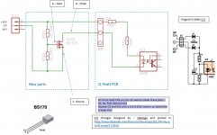
I'm not sure I understand exactly how the old circuit and the new circuit are supposed to work.
But I try to explain what I see.
Old circuit.
40V arrives at K7. Flows through either diode to leave ~39.3V at R19.
assume 1.5Vf through the LED. That creates a current of 1.25mA through R28.
Current through R19 = {39.3-1.5} / 27k = 1.4mA
Therefore current through LED ~ 1.4-1.25 = ~0.15mA
That seems a bit low
New circuit.
16+16Vdc arrives at K7 after the FET switches ON.
assuming the same 1.5Vf for the LED, the current flow through the two 1k5 resistors will be ~ {32-1.5} / 3k = 10.17mA
Current through LED will be 10.17-1.25 = ~8.92mA
That seems high. Why such a big change from 0.15mA to 8.92mA?
Current through the new resistor R101 & R102
32V/140r = 228.6mA
WHY?
Pdis in R102 = 0.2286²*20 = ~1W
Pdis in R101 = 0.2286²*120 = ~6W
Why?
Last edited:
I'm not sure I understand exactly how the old circuit and the new circuit are supposed to work.
But I try to explain what I see.
Old circuit.
40V arrives at K7. Flows through either diode to leave ~39.3V at R19.
assume 1.5Vf through the LED. That creates a current of 1.25mA through R28.
Current through R19 = {39.3-1.5} / 27k = 1.4mA
Therefore current through LED ~ 1.4-1.25 = ~0.15mA
That seems a bit low
I'm personally not using this setup because I'm using SMPS (so I don't have 40 volts AC) but it seems to work well since many other people have build the amp succesfully.
New circuit.
16+16Vdc arrives at K7 after the FET switches ON.
assuming the same 1.5Vf for the LED, the current flow through the two 1k5 resistors will be ~ {32-1.5} / 3k = 10.17mA
Current through LED will be 10.17-1.25 = ~8.92mA
That seems high. Why such a big change from 0.15mA to 8.92mA?
Current through the new resistor R101 & R102
32V/140r = 228.6mA
WHY?
Pdis in R102 = 0.2286²*20 = ~1W
Pdis in R101 = 0.2286²*120 = ~6W
Why?
16+16Vdc ????
I'm using +16 volts of the AUX output. So your calculations are incorrect.
I do however use a quite high current (about 100 mA) in the voltage divider. As mentioned previoulsy, I do that to discharge the power supply's output caps fast. That will also help disengage the speaker relay faster when power is removed.
9 mA to drive a LED is not high at all... Moreover, according to the datasheet of the 4N25, the LED current can be as high as 50mA (which is high)... But in the above case, the LED current is about half of what you calculated (16 volts supply, not 16 + 16); in other words about 16 - 1.2 / 3000 = 4,9 mA.
Old circuit.
If that 40V is 40Vac, then the peak current will be ~ 50% higher than the calculated 0.15mA I gave. ~ 0.2mA
New circuit
for a 16V supply it is much better than half.
{16V-1.5V}/3k = ~4.83mA
Subtract ~1.25mA through the byapss resistor gives ~3.6mA through the LED. That seems much more sensible. I'm glad you were awake and corrected my mistakes.
What a pleasure to see the experts with the calculations, which has now been settled, with thanks to delange for the Cct.
Mounting transistors on Heatsink hopefully tomorrow and then wire up begins...
Mounting transistors on Heatsink hopefully tomorrow and then wire up begins...
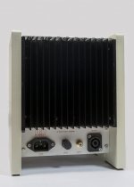
Finished the enclosure of my first channel this week. I have been debating what kind of finish to use; I've considered carbon fiber, aluminum and wood. I finally decided to use wood and paint it in a light color. Since the amplifier will be sitting behind the speaker, the idea is to be "incognito" as possible.
During my testing I've use the amplifier on the floor and against the wall behind the speaker. The heatsink is facing the speaker so that the connectors and volume pot is easy accessible.
Using the amplifier showed that I would like a power LED to indicate it's powered on. I will be modifying this channel during the course of next week.
I wounder how the projects of Calpe and Popchops are coming along...
Attachments
Last edited:
delange, your's look great with a great finish too.
I'm delayed, but hope to mount transistors on heatsinks this week and wire up etc.
I see you have a level control at the rear, could you explain a little?
I'm delayed, but hope to mount transistors on heatsinks this week and wire up etc.
I see you have a level control at the rear, could you explain a little?
Last edited:
I see you have a level control at the rear, could you explain a little?
Many devices use a very high output signal today. The "standard" seems to have evolved to 2 volts for 0 dB. As you have seen in the specs, the Q-Watt amplifier input sensitivity is 0,88 volts for 137 watts (0.1% THD+N).
This means that you would need to use an attenuator in the chain in order to keep the amp in its safe area. That's why I have built in a potmeter to adjust the level (volume if you like).
delange, that was my thought when I questioned the Elektor techs about the levels and I was more or less told to keep the volume low!
May I ask in what way have you used a 'potmeter'?
Cheers
May I ask in what way have you used a 'potmeter'?
Cheers
- Home
- Amplifiers
- Chip Amps
- My Q-Watt project