Hiya,
I too have been following the project on Elektor Labs.
I'm interested to have some views/feedback on cases to fit two Q-Watt boards and two SMPS's inside one case.
Cases... that is a very personal choice I would say. It comes down to personal preference. As mentioned in my initial post, I'm building a custom designed case. One of my objectives for this project is to 'hide' the amplifier behind the speakers. You will probably have different objectives...
There is a popular manufacturer that you might want to check out: Modushop by Hi-Fi 2000 | Contenitori per Elettronica | Electronic Enclosures | Hi Fi Chassis
I'm sure you will find an enclosure that you like and fits your needs (size, looks, etc).
I'll post more pictures of my project as it progresses.
Apart from that having ordered the recommended heatsinks, i assume they have to be mounted so that the 'fins' point out, rather than lay the heatsink flat with the 'fins' pointing downwards?
Andrew already pointed out what is important when mounting / using heat sinks so I won't repeat that.
But while sourcing an enclosure, you might want to look at the enclosures with "build in" heat sinks. Just be sure to check if the model you select is sufficient to keep the Q-Watt cool.
there is no overcurrent, or short circuit protection, and no clip protection.
trusting all that available power to a single pair of output transistors seems optimistic to me. why not add a few more power transistors in paralell ?
I'm not worried about all those things. My extremely loud playing music days are over 😛
Besides that, the Q-Watt designers idea behind the project was to create a simple amplifier with decent specifications. That's the reasons why it doesn't come with a lot of whistles and bells.
People are still free to implement more bells and whistles if they like. That's the beauty of diy I guess.
Q-Watt heatsinks
That being the case the recommended heatsinks will be binned and is a waste of money, seeing that in the Elektor article their downfall is that they have not recommended any type of case to use.
https://www.modushop.biz/site/index.php?route=product/category&path=66_95_101
https://www.modushop.biz/site/index.php?route=product/category&path=204_206
Unless I'm overlooking something, the site does not mention the thermal resistance of their heat sinks (on the links you provided above).
Anyway, if you prefer the use the heat sinks you already bought then you could look at the enclosures without a heat sink:
Slimline:
https://www.modushop.biz/site/index.php?route=product/category&path=20
Pesante:
https://www.modushop.biz/site/index.php?route=product/category&path=65
A 3U enclosure is a bit higher than the 100 mm height of the SK45 heat sink and would be a possible candidate.
Yep, the Modushop lacks information and i have today made some enquiries to them.
I really would like to use the heatsinks ive purchased at 17 pound each , so lets see
I really would like to use the heatsinks ive purchased at 17 pound each , so lets see
Last edited:
These are more than sufficient for the Q-Watt.
iirc, they are 300W devices, semelab also makes 400W devices but in a TO-264, same lead spacing.trusting all that available power to a single pair of output transistors seems optimistic to me. why not add a few more power transistors in parallel ?
Q-Watt - heatsinks
cheers Delange for the confirmation.
I'll have to check measurements etc. to be able to order a case, i really need to give a big push on this to put it all together and test!
cheers Delange for the confirmation.
I'll have to check measurements etc. to be able to order a case, i really need to give a big push on this to put it all together and test!
iirc, they are 300W devices, semelab also makes 400W devices but in a TO-264, same lead spacing.
Yes, these are nice devices. Shame that they are discontinued.
I ordered a few for spare the other day.
Another update on the project.
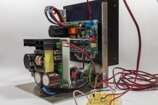
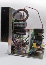
It is all slowly coming together. Yesterday I replaced the potmeter by a 12 turn potmeter from Vishay. Adjusting the idle current is a breeze now.
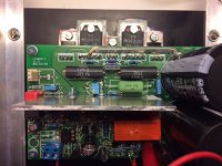
I did some testing with a FET switch in order to switch off the relay immediately when the amp is switched off. Since I'm using an SMPS I needed to modify the circuitry around the voltage guard. I'm using the SMPS's aux output for that but the buffer caps fitted on there are quite large and kept the relay on too long. The FET switch solves that. I need to find a nice way to install the circuitry in the amp. A part of the FET switch circuitry is on the test board in the attached pictures.
I put the enclosure together and finished the cabling in the amp. The enclosure is not finished yet though. I still need to build the rest of the enclosure. But I'm still toying with a few options for that in my mind.
Up until now I've been testing the amp with some cheap speakers I use for testing. The amp sure sounds promising and I'm thinking of connecting the amp to better speakers tomorrow to have a listen.
It is all slowly coming together. Yesterday I replaced the potmeter by a 12 turn potmeter from Vishay. Adjusting the idle current is a breeze now.
I did some testing with a FET switch in order to switch off the relay immediately when the amp is switched off. Since I'm using an SMPS I needed to modify the circuitry around the voltage guard. I'm using the SMPS's aux output for that but the buffer caps fitted on there are quite large and kept the relay on too long. The FET switch solves that. I need to find a nice way to install the circuitry in the amp. A part of the FET switch circuitry is on the test board in the attached pictures.
I put the enclosure together and finished the cabling in the amp. The enclosure is not finished yet though. I still need to build the rest of the enclosure. But I'm still toying with a few options for that in my mind.
Up until now I've been testing the amp with some cheap speakers I use for testing. The amp sure sounds promising and I'm thinking of connecting the amp to better speakers tomorrow to have a listen.
Attachments
Cases...
I agree with using a case with integrated heatsinks. They need to be so large it's the most practical solution.
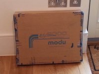
Modushop by Hi-Fi 2000 | Contenitori per Elettronica | Electronic Enclosures | Hi Fi Chassis just sent me a 3U Dissipante case with internal size 360x300x120. I'm aiming to put full dual mono system in this with 2x linear power supplies.
I ordered a spare backplate, so I can mess around with a few output connectors before machining the final article.
I agree with using a case with integrated heatsinks. They need to be so large it's the most practical solution.
Modushop by Hi-Fi 2000 | Contenitori per Elettronica | Electronic Enclosures | Hi Fi Chassis just sent me a 3U Dissipante case with internal size 360x300x120. I'm aiming to put full dual mono system in this with 2x linear power supplies.
I ordered a spare backplate, so I can mess around with a few output connectors before machining the final article.
Attachments
Yesterday I replaced the potmeter by a 12 turn potmeter from Vishay. Adjusting the idle current is a breeze now.
Delange - Which part number? Sorry if you already said, but I could not find one with same pin spacing. Did you have to bend it around much?
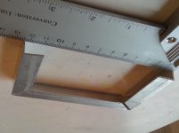
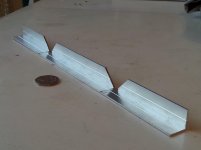
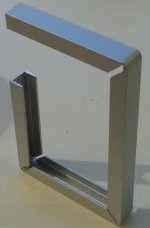
PCB mounting to heatsink
I tried cutting 45deg slots in 15x15mm angled aluminium to form the pcb holder. Was quite successful, but the one - sided angled stiffener tends to warp the top surface when bending by hand. U - section aluminium would work better. Might try that after a few shandies later.
I tried cutting 45deg slots in 15x15mm angled aluminium to form the pcb holder. Was quite successful, but the one - sided angled stiffener tends to warp the top surface when bending by hand. U - section aluminium would work better. Might try that after a few shandies later.
Attachments
Last edited:
Delange - Which part number? Sorry if you already said, but I could not find one with same pin spacing. Did you have to bend it around much?
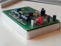
I used a 12 turn Vishay potmeter. It is quite a bit smaller than the original potmeter but it is very easy to mount it.
Vishay 74W 500R Spindeltrimmer 12-slagen Lineair 0.25 W 500 ? 4320 ° 1 stuks in de Conrad online shop | 423947
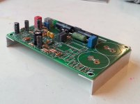
You actually would only need to bend the middle pin. The other two pins fit directly in the holes on the pcb. However, I did bend all three pins to move the potmeter a bit to the left. This is easier for adjusting reasons. The adjust screw would otherwise be directly underneath the screw that holds the heat sink to the LME49811. I have attached a (crappy) picture of my pcb.
Attachments
Last edited:
I tried cutting 45deg slots in 15x15mm angled aluminium to form the pcb holder. Was quite successful, but the one - sided angled stiffener tends to warp the top surface when bending by hand. U - section aluminium would work better. Might try that after a few shandies later.
Nice work.
From looking at the pictures I think you might have some trouble with the two mounting screws on the back (on the transistors side). These holes seem to fall right into the cut in the aluminium bracket.
I am a bit behind you guys with the construction. I need to mount the aluminum heatsink and begin to wire up.
Looks like i'll follow 'popchops' and get a 3U Dissipante case from Modushop.
Popchops as you plan to mount dual Q-Watt boards, you'll be using their heatsinks?
Which ones?
I assume that the guys having problems with the quiescent current replaced the trimmer capacitor and fitted the 18pf?
If the case having fitted the 18pf is still tricky then it'll have to be a Vishay or similar preset.
I assume that the guys having problems with the quiescent current replaced the trimmer capacitor and fitted the 18pf?
If the case having fitted the 18pf is still tricky then it'll have to be a Vishay or similar preset.
Calpe, the cap trimmer has nothing to do with the idle current.
I replaced potmeter P1 with a Vishay multi turn potmeter. It is P1 who is responsible for setting the idle current.
I think you might have some trouble with the two mounting screws on the back (on the transistors side). These holes seem to fall right into the cut in the aluminium bracket.
You are right... I haven't really decided what to do about that. I am working on neater cuts with u - section ally, but still one bolt will fall in the crack. I might just put a big washer on each side and use nut and bolt.
I have never mounted a PCB: what kind of spacers should be used to lift up the PCB off the bracket and to insulate?
Attachments
Last edited:
I have never mounted a PCB: what kind of spacers should be used to lift up the PCB off the bracket and to insulate?
I typically use metal standoffs with M3 thread. Depending on the situation, these are either female - female or sometimes male - female.
https://cdn.sparkfun.com//assets/parts/4/9/5/4/10463-01.jpg
Attachments
![10463-01[1].jpg](/community/data/attachments/532/532932-db1ac47a8a3d61924001e1194a5a2c75.jpg?hash=2xrEeoo9YZ)
- Home
- Amplifiers
- Chip Amps
- My Q-Watt project