Messed up the capacitor, quote - "C3 is needed for the frequency compensation of the i.c."
Delange, from where can the Standoff's be obtained?
Surprised though that the Elektor team didn't have problems with the adjustment of P1.
Quote - "Slowly turn P1 to the right (clockwise) until the current increases by 30 mA (60 mA total). This relatively low quiescent current is more than adequate. The quiescent current will rise slightly as the heatsink temperature increases. However, it will normally remain below 90 mA."
In my view looking at the Elektor project it lacks a lot of basic information especially on case types and construction.
Last edited:
Make i ask (not having constructed anything for a long time) what is the best thing that can be used to label the sockets etc.?
Make i ask (not having constructed anything for a long time) what is the best thing that can be used to label the sockets etc.?
I use Front Panel Designer from Schaeffer: https://www.schaeffer-ag.de/en/
Depending on the project, I use it to actually have a front (or back) panel constructed.
In other projects, such as the Q-Watt, I kind of cheat with Front Panel Designer: I use it to create the panel. I then print that on an A4 sheet label with my inktjet printer. After applying the label to the enclosure I use adhesive transparent plastic foil over the paper label for protection.
see picture in the first post for an example.
Thanks for the info it helps a lot
Delange, from where can the Standoff's be obtained?
Everything has to be couriered here and pay import duty, which make building prices expensive.
As I said if the Elektor write up had more constructors ideas and information it would have helped a hell of a lot.
Thanks
Delange, from where can the Standoff's be obtained?
Everything has to be couriered here and pay import duty, which make building prices expensive.
As I said if the Elektor write up had more constructors ideas and information it would have helped a hell of a lot.
Thanks
Last edited:
Thanks for the info it helps a lot
Delange, from where can the Standoff's be obtained?
The usual suspects such as Farnell, RS, Conrad, etc.
Example at RS: Threaded Standoffs | Threaded Standoffs - for online sales of Spacers & Standoffs| RS Components
Popchops, can you tell me what heatsinks you purchased from Modushop for the U3 Dissipante case?
As you know the original ones in the Elektor article were '0.7 °C/W, 40 mm, 200 mm, 100 mm Farnell Code no. 4621890'.
As you know the original ones in the Elektor article were '0.7 °C/W, 40 mm, 200 mm, 100 mm Farnell Code no. 4621890'.
Last edited:
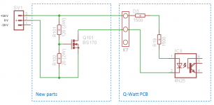
For those of us using a switched mode power supply instead of a traditional power supply with transformer, bridge and caps will need a slight modification to the way the "voltage guard" is implemented on the Q-Watt. The original design uses the dual 40 volts AC from the transformer to feed a 4N25. When this voltage is not present then the speaker relay will not be switched on.
The idea is that the relay is switched off as soon as the power is removed to the amp.
With the SMPS there is no dual 40 volts AC. Instead I'm using the aux output of the SMPS for this purpose (dual 16 volts). In order to make the relay switch off immediately when the power is switched off I used a FET as a switch together with a voltage divider. The divider is set to draw about 100 mA so that the buffer caps discharge relatively fast when the power is removed.
On the Q-Watt PCB you do not need to solder the parts D3, D4, R19, R20 and C14. I used a 1k5 resistor for D3 and R19 on the Q-Watt PCB. The voltage devider and the FET are external to the Q-Watt PCB (on a breadboard). The simple schematic is attached.
Attachments
delange, that includes me on the SMPS list, many thanks for the modification.
Might be a good idea to post this information on Elektor Labs: -
https://www.elektormagazine.com/labs/q-watt-simple-audio-power-amplifier-110656
Why such high wattage resistors for R101, 120R 3W (RS Code
485-1903?) and R102, 20R 2W (RS Code 850-5512?) ?
The BS170 can be found here BS170 | Fairchild BS170 N-channel MOSFET Transistor, 0.5 A, 60 V, 3-Pin TO-92 | Fairchild Semiconductor
Why such high wattage resistors for R101, 120R 3W
That resistor is dissipating 1.5 watts. It is good practice to double the resistor power rating. Notice that the 20 ohms resistor is a 2 watt version.That one is dissipating a lot less.
https://www.elektormagazine.com/labs/q-watt-simple-audio-power-amplifier-110656
Why such high wattage resistors for R101, 120R 3W (RS Code
485-1903?) and R102, 20R 2W (RS Code 850-5512?) ?
The BS170 can be found here BS170 | Fairchild BS170 N-channel MOSFET Transistor, 0.5 A, 60 V, 3-Pin TO-92 | Fairchild Semiconductor
The 1K5 resistors i assume are 0.25W?
Why such high wattage resistors for R101, 120R 3W (RS Code
485-1903?) and R102, 20R 2W (RS Code 850-5512?) ?
The BS170 can be found here BS170 | Fairchild BS170 N-channel MOSFET Transistor, 0.5 A, 60 V, 3-Pin TO-92 | Fairchild Semiconductor
The 1K5 resistors i assume are 0.25W?
Q-Watt PCB's
If anyone is interested i have a new (spare) unused Q-Watt pcb (no components).
Q-WATT – AUDIO POWER AMPLIFIER (110656-1).
For £18 it's your plus package & postage.
If anyone is interested i have a new (spare) unused Q-Watt pcb (no components).
Q-WATT – AUDIO POWER AMPLIFIER (110656-1).
For £18 it's your plus package & postage.
If anyone is interested i have a new (spare) unused Q-Watt pcb (no components).
Q-WATT – AUDIO POWER AMPLIFIER (110656-1).
For £18 it's your plus package & postage.
Are you giving up your Q-Watt project?
Popchops, can you tell me what heatsinks you purchased from Modushop for the U3 Dissipante case?
As you know the original ones in the Elektor article were '0.7 °C/W, 40 mm, 200 mm, 100 mm Farnell Code no. 4621890'.
Hi Calpe,
Yep the 300mm x 3U Dissipante case includes two 300x120x40mm heatsinks that form the case walls. Far exceeds the spec because I need the depth.
Hi guys.
Give up? Never!
It's damn annoying though that so many bits and pieces are needed and i can't source them locally.
Farnell & RS must be happy with me!
Popchops, thanks immensely for the case dimensions etc.
Popchops, as you have probably seen the heatsink in Elektors project is listed as '0.7 °C/W' - height 40 mm, width 200 mm and depth 100 mm.
Not sure if i'm looking at the correct Modshop case, as i thought the temperature coefficient was fractionally lower at 0,5 C°/W?
To make sure i order the correct one have you please got the Modshop order no. for the 300mm x 3U Dissipante case?
And also the rear/front plate, please.
Cheers
Last edited:
Popchops, as you have probably seen the heatsink in Elektors project is listed as '0.7 °C/W' - height 40 mm, width 200 mm and depth 100 mm.
Not sure if i'm looking at the correct Modshop case, as i thought the temperature coefficient was fractionally lower at 0,5 C°/W?
To make sure i order the correct one have you please got the Modshop order no. for the 300mm x 3U Dissipante case?
And also the rear/front plate, please.
Cheers
Hi Calpe! The dissipation coefficient of my heatsinks I would expect to be about 0.5 deg C per Watt. This is better than the 0.7 required by Elektor I.e. lower temperature at the same power.
The 3U case is the one with internal dimensions 360 (w) x 300 (d) x 120 (h) in millimetres. See Modushop part numbers below:
Dissipante 3U 300mm 10mm BLACK front panel - 3mm aluminium covers and rear panel: 1NPDA03300N
Inner baseplate for Dissipante 300mm: 1BASEPD300
Kit of 4 antivibrations feet: KITPDAMM
Last edited:
Mouser have steel standoffs of different heights with 2mm thread. Just ordered some of these for a quick look:
https://www.mouser.co.uk/Search/ProductDetail.aspx?R=9774040243Rvirtualkey51110000virtualkey710-9774040243R
https://www.mouser.co.uk/Search/ProductDetail.aspx?R=9774040243Rvirtualkey51110000virtualkey710-9774040243R
Last edited:
Hi popchops. Many thanks for your help with the case.
Order will be sent today.
Here's a quick photo of the 3U 300mm deep case. The 2U case I think has adequate cooling but my caps won't fit so I went for 3U.
I was a bit disappointed with the feet. Poor quality.
Attachments


- Home
- Amplifiers
- Chip Amps
- My Q-Watt project