Tom , after I read the description of Modulus-86 Rev. 3.0 on your web site I found the answers for most of my questions . Sorry for wasting your time.
I always try to solder the semiconductors touching a sort of heatsink, that's why I was a little bit surprised to see you removing the board and soldering the chip with no heatsink contact.
I always try to solder the semiconductors touching a sort of heatsink, that's why I was a little bit surprised to see you removing the board and soldering the chip with no heatsink contact.
I don't think any power amplifier has an issue with being soldered while not being cooled (hey, a measly TO-92 transsitor or SSOP8 Op-Amp can withstand that). The only reason I can think of for doing it the other way around is that there is less chance of mechanically stressing the pins if the PCB is going to be mounted on the chassis. But this is the reason the LM3886 has those S-shaped pins - mechanical decoupling.
Not necessarily. There's a common misconception that balanced/differential is always better. Sometimes a balanced circuit can be made to provide better performance, but it's not a universal truth.
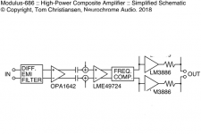
So that block diagram came from the Modulus-686, which does provide better performance than the Modulus-86. But if you simply take out four of the LM3886es, you'll end up with a circuit that can't drive 4 Ω speakers unless you lower the supply voltage to the point where it becomes pointless. You can read about that here: Taming the LM3886 Chip Amplifier: Output Power – Neurochrome
Tom
Hi Tom, I got a little tired of the groud loop I had a problem with in my combination First Watt B1 Korg pre and Mod-86. So it was on ice until now. I changed the volum pot in the pre and grounding in the pre as I thought it could be the problem. Then I went the whole way with diodebridge/resistance/cap between signal ground and chassis in the mod-86. The combination of this pre and mod-86 still had problems. The I tried grounding the - ( negative) out (at the phono plug in mod-86) first to chassis and then via diodebridge/resist… etc. The issue dissapered and great music resulted.
It seems that the output of the mod-86 is not grounded at all via the power supply ground as I thought it was, I use plastic print standoffs. So I need to connect one of the minus/ground (1 & 3 are connected at the print as Im using rca phono out and not xlr ) to ground/chassis.
Maybe in the manual page 39 the rca shield should have black dot to illustrate it needs to be grounded to chassis.
Last edited:
I have played a variety of music and the combination B1 Korg ( adjusted to very moderate amount of 2. harmonic) & Mod-86 is great. Im using this on my uppgraded Carlsson OA-51 speakers in our living room. My Altec A5s are out of sight ") in my den in the cellar, look forward to try the combo there.
in my den in the cellar, look forward to try the combo there.
in my den in the cellar, look forward to try the combo there.You may note that in the diagram on page 39 (Rev. 2.4 doc) the power supply ground (i.e., the centre point between the reservoir caps) goes to the same grounding point on the chassis as the mains ground. You need to make that connection with a wire.
I would never rely on standoffs for grounding. Not in an audio circuit anyway. In RF circuits you sometimes have to use standoffs or RF gaskets for grounding.
Either way. I'm glad you got it working. Thank you for following up.
Tom
I would never rely on standoffs for grounding. Not in an audio circuit anyway. In RF circuits you sometimes have to use standoffs or RF gaskets for grounding.
Either way. I'm glad you got it working. Thank you for following up.
Tom
As long as you're happy life is good.
I have seen SMPS-powered line-level audio circuits output hum if their chassis wasn't grounded. In my case I ended up grounding the chassis to the RCA input ground. I wonder if that's what's going on for you. Basically by grounding the RCA you end up grounding the Korg chassis and the hum goes away.
Tom


There absolutely is a checklist. See page 31 of the design doc. (MOD86 Rev. 2.4)
You can take it a step further by testing the ±16 V supply provided by U5 and U6 before you plug in the 8-pin ICs. I used to include this in the Final Test procedure, but it seemed to raise more questions than it was worth. Given your oopsie with U5 it's worthwhile to go through this:
Assemble the board completely but leave the three 8-pin ICs out of their sockets. If you've already stuffed those ICs I'd probably leave them in as U5 is probably OK. Or you can pry the ICs from their sockets. Just be careful not to bend their pins.
Inspect the board for solder bridges and cold solder joints. Fix as necessary. Apply ±20-30 V from a current limited power supply. Measure the voltage from pin 4 and pin 8 of U4 to ground. You should have -16 V (±1 V) on pin 4 and +16 V (±1 V) on pin 8. You should also have lowish DC offset at the output of the amp. Without the DC servo it should be below 110 mV.
If you don't have a current limited power supply, you can create one by inserting a 10 Ω, 0.25 W resistor in series with each supply lead (i.e., V+ and V-). If there's an issue with the amp those resistors will go up in smoke when you turn the power on.
If the resistors survive power-on, measure the ±16 V supply and DC offset as outlined above.
Then plug in the 8-pin ICs, remove the 10 Ω resistors on the supplies (if applicable), power up again and measure the DC offset on the amp. You should see below 1 mV. My builds typically sit around 50-100 uV. Note that to get into the uV offset levels you need to remove the flux from the board to prevent the leakage currents flowing in the flux from degrading the DC performance. You'll also likely need a bench top DMM to measure offset that low.
I generally recommend running a sine wave through the amp and measuring the gain. That's just a sanity check. You should have a gain of 10 V/V (20 dB) if the board is built according to the BOM. The design doc does list the resistor changes needed for different gains.
Tom
Hello Tom,
Apologies for the delay but work doesn't agree with my project time at the moment...
I still have a few questions regarding the test procedure for the possible problem with U5 and U6.
So the boards are assembled, the 3 8pin ICs are missing.
Do I need a heatsink for this test?
Is it correct that the pins are numbered anti clockwise, so pin 8 is opposite pin 1 and pin 5 is oppsite pin 4? So I want to measure the bottom left pin (4) and the top right pin (8)?
Where do I get ground from to measure pin 4 and pin 8 of U4? The center pin of the PSU input? I'm using a 3-channel desktop psu with tracking so I managed to get -20V, common ground and +20V which I confirmed with the multimeter. I set the current so it's just enough to get a stable voltage. I assume I'll have to turn that up once a load is connected. How much current would be acceptable to reach stable 20V, or at how many mA do I have to start worrying?
For the wooden parts of the enclosure I'm using copper foil with conductive glue. I don't have a real heatsink, one side panel of the enclosure is a 300x100x15mm solid piece of aluminium which I hope will be sufficient. The rear panel for the connectors is 3mm aluminium. Base, front and the other side panel are plywood.
I shot a Fluke 179 on ebay to replace the old multimeter. It looks like solid investment, I should have done that years ago...
I'm a bit nervous to apply power to the boards. It should be OK with the benchtop psu but once it goes on the mains with the transformer and the power-86 I'm hoping to find a friend with a bit more experience with AC power circuits.
Thanks a lot
Stefan
Last edited:
Actually, the Modulus-86 clips a little bit earlier (a few hundred mV) than the naked LM3886, so on ±28 V rails, the power out is 35 W (8 Ω) and about 65 W (4 Ω). The naked LM3886 will provide 38 W, 68 W respectively under the same conditions. The naked LM3886 will also provide 100x worse THD, but that's another matter...
~Tom
Can you plz explain this? Thanks
Do I need a heatsink for this test?
Not if you don't connect a load/speaker.
Is it correct that the pins are numbered anti clockwise, so pin 8 is opposite pin 1 and pin 5 is oppsite pin 4? So I want to measure the bottom left pin (4) and the top right pin (8)?
If you place pin 1 in the top left, those coordinates check out.
Where do I get ground from to measure pin 4 and pin 8 of U4? The center pin of the PSU input?
Yep. Or pin 1 of the input connector.
I'm using a 3-channel desktop psu with tracking so I managed to get -20V, common ground and +20V which I confirmed with the multimeter. I set the current so it's just enough to get a stable voltage. I assume I'll have to turn that up once a load is connected.
Perfect! I would set the current limiter to something like 200-500 mA. You'll find that the current meter pegs at that value when you first turn on the supply. The output voltage will build to ±20 V and the current then settle at about 85 mA (more like 60-65 mA if you have the 8-pin ICs out).
If you can't get the supply to provide ±20 V when it's set to 200-500 mA, you have issues.
I don't have a real heatsink, one side panel of the enclosure is a 300x100x15mm solid piece of aluminium which I hope will be sufficient.
That's a decent amount of thermal mass, but not much of a radiator. It'll probably get pretty toasty if you crank the amp for any length of time. I suppose you can try it out and see what happens, but I would plan to use an actual heat sink - or at least put a thermal switch on the block of aluminum.
Sorry... Physics...
I shot a Fluke 179 on ebay to replace the old multimeter. It looks like solid investment, I should have done that years ago...
That's how I've generally felt when I finally cave and buy a good tool.
[...]but once it goes on the mains with the transformer and the power-86 I'm hoping to find a friend with a bit more experience with AC power circuits.
That's probably a good approach. I recommend testing the power supply once you have it connected to the power transformer. Verify that it provides about ±28-30 V out. The voltage will be a bit high when the supply runs without the amp modules, so you may see ±32-33 V. That's normal.
Once you've verified that the power supply works, turn the power off, wait for the supply caps to discharge, then hook it up to the amp modules.
Tom
Can you plz explain this? Thanks
I thought what I wrote was pretty clear. Would you specify what you would like me to explain exactly?
Tom
- Home
- Amplifiers
- Chip Amps
- Modulus-86 build thread